9
4. Firmly seat the adapter in the serial port. Screw down the adapter to secure it to
the serial port.
5. Insert one end of the serial cable into the adapter until a click is heard. Insert the
other end of the serial cable into port "A" of the control card, again until a click is
heard.
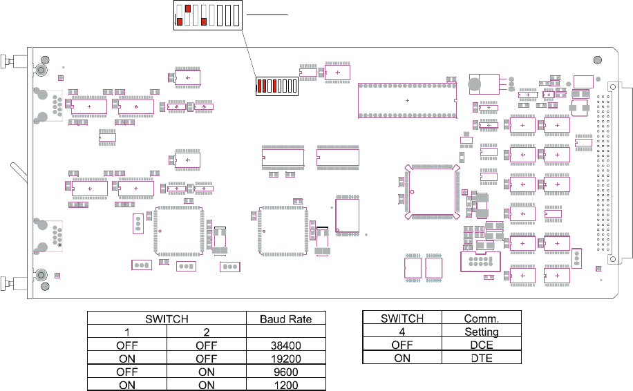
Fig. 2 Control Card Layout with DIP Switch Settings.
6. Press <ENTER> on the keyboard. The LCI3200>> prompt should appear. If
not, check that the ConsoleServer 3200 is connected to the appropriate power
outlet, the power switch is on, the control card is firmly seated, and that all cable
connections are secure. If "garbage" characters appear on the screen, check
that the communications settings are correct.
7. The system administrator may now login (as outlined in Section 6.0, System
Administrator) into port "A" of the control card.
The system administrator may not access attached devices. To access attached
devices, a user profile must be created (see section 6.2), and the user must log in
through one of the user access cards (see section 3.3).
U50
U45
U21
U23
U44
U26
U27
U29
U28
U30
U48
U40
U39
U33
U34
Q1
U36
U37
U38
RP1
RP 2
RP3
RP4
RP5
TP 1
TP2
TP 3
TP4
U49
U52
C19
C8
C11
C15
C16
C5
U42
U55
C1
C10
C12
C13
C14
C17
C18
C2
C20
C3
C4
C6
C9
RP6
U53
U54
U58
U59
U62
U35
U63
C10 2
C10 3
C41
C42
C48
C50
C51
C52
C53
C55C56
C57
C58
C59C60C61
C62
C63
C64
C70
C77C78
C82
C84
C93
C94
C95
C96
C97 C9 9
L1
L2
L3
L4
R1
R10
R11
R12
R13
R2
R3
R4
R5
R6
X2
Y1
U56
U57
U51
U60
C21
C22
C23
C24
C
2
5
C26
C27
C30
X1 X3
X4
FID1
FID2
FID5
FI D6
C10 4
C105
J5
J6
J7
J8
U64
U65
U66
Y2
C54
J4
C32
C33
C34
C35
C36
J1
12345678
O
ROCKER DOWN
A1
B1
C1
A32
B32
C32
+
+
LIGHTWAVE COMMUNICATIONS, INC
ASSEMBLY 09.300.004
made in the USA
+
+
+
J3
P
2
P
1
H
1
H
2
C
7
S
W
3
ROCKER DOWN
21
F
F
O
543 768
DEFAULT DIP SWITCH SETTINGS
