


106 Appendix D: Technical information Matrox Meteor-II /Digital
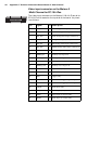
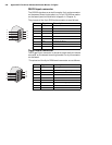
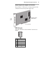
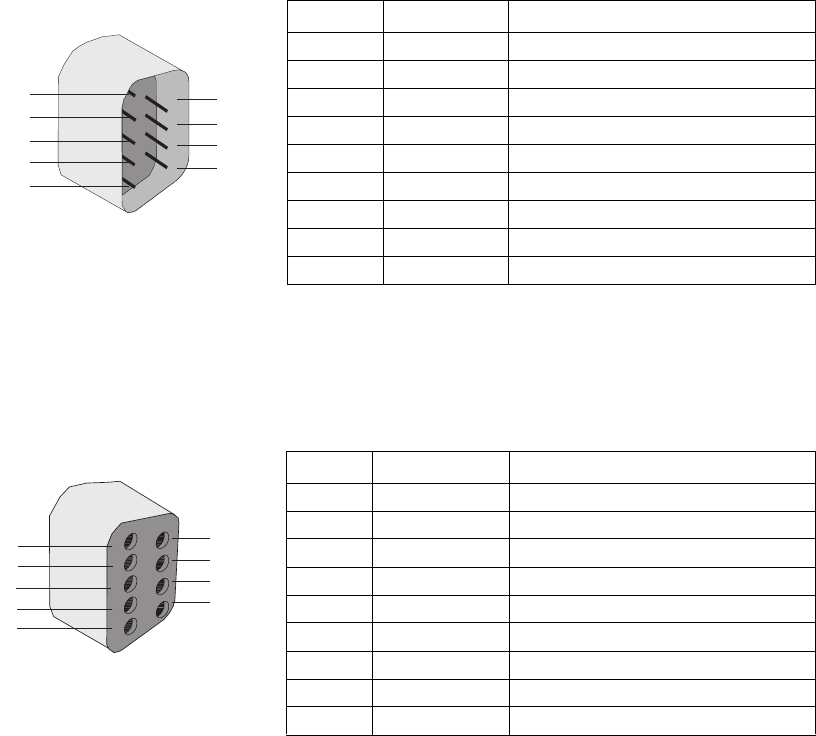
RS-232 input connector
The RS-232 signals are routed through a 9-pin male connector
on the second mounting bracket, to a 10-pin RS-232 connector
on the board (see the installation diagram in Chapter 2).
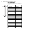
The pinouts of the 9-pin DB9 male connector are as follows:
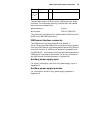
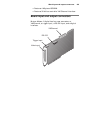
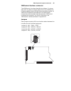
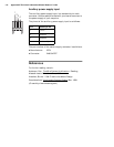
Trigger input connector
The trigger input connector is routed through the 9-pin female
connector on the second mounting bracket to a 4-pin connector
on the board.
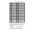
The pinouts of the 9-pin DB9 female connector are as follows:
Pin Signal Description
1 N/C Not connected.
2 RX Receive.
3TX Transmit.
4 N/C Not connected.
5 GND Ground.
6 N/C Not connected.
7 RTS Request To Send.
8 CTS Clear To Send.
9 N/C Not connected.
Pin Signal Description
1 TTL TRIG TTL trigger.
2 OPTO TRIG- Opto-isolated trigger (negative input).
3 N/C Not connected.
4 N/C Not connected.
5 N/C Not connected.
6GND Ground.
7 OPTO TRIG+ Opto-isolated trigger (positive input).
8 N/C Not connected.
9 N/C Not connected.
1
2
3
4
5
6
7
8
9
1
3
4
5
6
7
8
9
2