


Matrox Meteor-II /Standard grab section 57
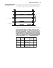
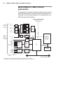
Trigger signals connected to the OPTOTRIG- and OPTOTRIG+
input pins, pass through an opto-coupler, a device that protects
the board from outside surges; OPTOTRIG- is usually
connected to the ground of the trigger source. The voltage
difference across OPTOTRIG+ and OPTOTRIG- must be
between 4.05 V and 9.16 V for logic high, and between -5.0 V
and 0.8 V for logic low. Refer to Appendix B for the pinouts of
these signals on your respective form factor.
User bits
Matrox Meteor-II /Standard supports four auxiliary user bits
through the video input connector: two input and two output.
These are available for controlling external events such as a
strobe light. User bits are programmed using the MIL-Lite
command MdigControl().
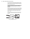
Using the auxiliary power supply
Matrox Meteor-II /Standard can supply power to your camera.
Use the 4-pin power cable provided with your board to connect
to the power supply of your computer. The operating voltage
can be set to either 5 V or 12 V, but the current drawn by all
cameras is limited to 1.5 A. The circuit uses an auto-resettable
fuse. For further information on connecting to the auxiliary
power supply connector, see the section, Connecting Matrox
Meteor-II /Standard to the auxiliary power supply input in
Chapter 2, and Appendix B. Note that this input is not available
on the CompactPCI and PC/104-Plus form factors.