


38 Chapter 2: Hardware installation
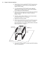
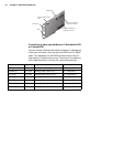
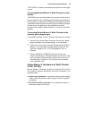
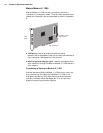
■ Auxiliary power supply input. Used to route power from
your computer through the Matrox Meteor-II board to your
camera.
■ Expansion module interface. Used to connect the optional
Matrox Meteor-II MJPEG module (for image compression
and decompression).
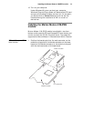
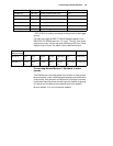
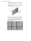
Connecting a video input to Meteor-II /Multi-Channel
Connect video sources to Matrox Meteor-II /Multi-Channel’s
video input connector, using the optional DBHD44-TO-8BNC
cable. This cable has eight BNC connectors and a 44-pin
high-density D-Subminiature plug. The wires of the cable are
color-coded as follows:
VMChannel
Video input
Auxiliary power supply input
Connector 1 (male) for
expansion module
Connector 2 (female) for
expansion module
Wires Signals Description
RED (1) VID1_IN1 Analog Video Input1, R
GREEN (2) VID1_IN2 Analog Video Input2, G
BLUE (3) VID1_IN3 Analog Video Input3, B
BLACK (4) SYNC_IN SYNC input
GREY (5) OPTOTRIG* External trigger input
WHITE (6) VID2_IN1 Analog Video Input4, R
YELLOW (7) VID2_IN2 Analog Video Input5, G
PURPLE (8) VID2_IN3 Analog Video input6, B