


Multiple board installation 49
Installing multiple
PC/104-Plus modules
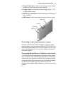
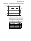
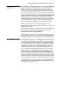
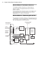
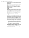
You can stack a maximum of four PC/104-Plus modules, shown
in the diagram below. Note that if you have PC/104 modules in
your computer, they must be placed at the top of the stack.
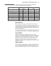
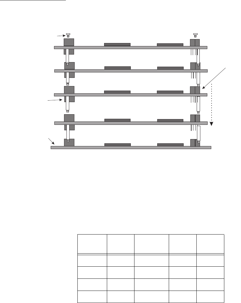
In addition, you must set the rotary switch of each PC/104-Plus
module to a unique setting in the stack. Setting the rotary
switch dedicates a group of PCI signals to the module in the
stack: clock, request grant, ID select, and interrupt signals. It
is recommended that the first module installed (the module
closest to the Host CPU board) be configured to 0, the second
1, and so on. The table below shows the recommended switch
setting for each module, as well as the dedicated signals.
PCI connector
Host board
ISA connectors
Top screw
Switch
position
Module
position
Interrupt Request
grant
ID
select
0 or 4 1 Interrupt A 0 0
1 or 5 2 Interrupt B 1 1
2 or 6 3 Interrupt C 2 2
3 or 7 4 Interrupt D 2 3