


32 Chapter 2: Hardware installation
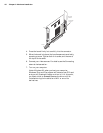
2. Once the boards are perfectly aligned, press the module
firmly but carefully into the connectors.
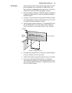
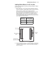
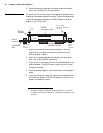
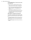
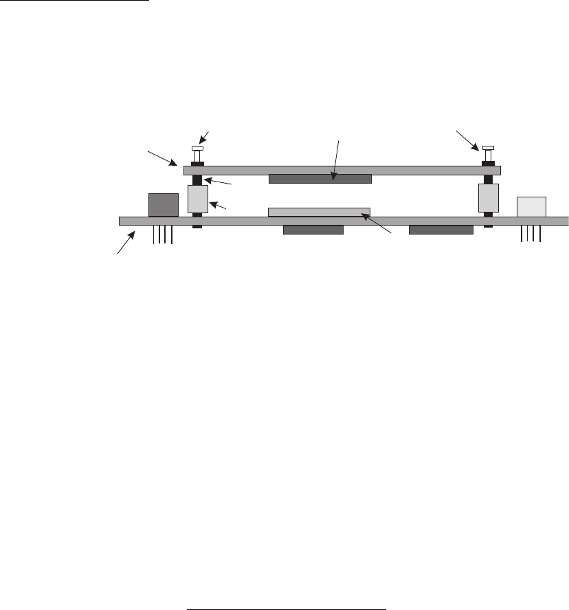
PC/104-Plus form factor On the PC/104-Plus form factor, the expansion connectors are
located on the soldered side of the board. Follow the steps below
to connect the Matrox Meteor-II MJPEG module to Matrox
Meteor-II for PC/104-Plus
1
:
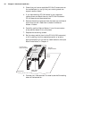
1. Align the connectors of the Matrox Meteor-II MJPEG
module with the expansion module connectors on the
Matrox Meteor-II board.
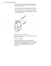
2. Position the spacer between the boards over each small
hole, next to the MJPEG connectors.
3. Insert the rivet into each hole from the soldered side of the
Matrox Meteor-II MJPEG module, ensuring that it goes
through the spacer.
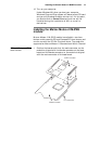
4. Press the boards together, so the connectors are snapped in
place.
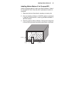
5. Insert the top pin through the hole from the soldered side
of the Matrox Meteor-II MJPEG module to hold the rivet,
spacer, and boards in place.
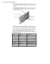
1. The Matrox Meteor-II MJPEG module 896-00 rev. A has two
connectors and two pins. 896-01 rev. A has three connectors and
five pins.
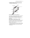
Meteor-II
PC/104-Plus
MJPEG
module
Component
side
MJPEG
connector (male)
Expansion module
connector (female)
Rivet
PC/104-
(PCI)
connector
Plus
PC/104
(ISA)
connector
Spacer
Top pin, spacer
and rivet at opposite side
of board
Top pin