


Matrox Meteor-II /Digital grab section 67
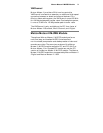
Auxiliary Seven general purpose auxiliary signals are supported: four
RS-422 or LVDS user signals (two input, two output), and three
TTL output signals. These are available for controlling external
devices, such as a strobe light. User signals are programmed
using the MIL-Lite command MdigControl().
Exposure Two timers in the PSG can generate two exposure signals
simultaneously. There are available in TTL or RS-422/LVDS
formats. Exposures are programmed using the MIL-Lite
function, MdigControl().
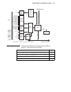
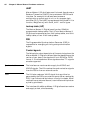
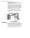
Trigger Three trigger inputs are routed directly to the PSG; the
interface supports TTL and RS-422/LVDS trigger input. In
addition, a trigger signal connected to the OPTOTRIG- and
OPTOTRIG+ input pins, passes through an opto-coupler, a
device that protects the board from outside surges; OPTOTRIG-
is usually connected to the ground of the trigger source. This
external trigger input allows image acquisition to be
synchronized with external events. The board can operate in
one of two modes, and the selected mode is specified by the DCF.
Matrox Meteor-II /Digital can operate in next valid frame/field
mode When in this mode, the digitizer waits for the next valid
frame or field (as specified by the DCF file) before commencing
the grab. This trigger mode functions in one of three ways:
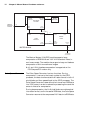
■ Edge-triggered monoshot acquisition: The VIA (Video
Interface Asic) waits for the rising/falling* edge to capture a
single frame.
■ Edge-triggered continuous acquisition: The VIA waits
for the rising/falling* edge to start a continous grab.
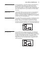
■ Level-sensitive "continuous" acquisition: The VIA grabs
continuously while the level of the trigger is high/low*.
* The polarity of the active and inactive levels of the trigger
signal are software programmable.
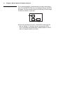
Matrox Meteor-II /Digital can also operate in asynchronous
reset mode. In this mode, the digitizer resets the camera to
begin a new frame when the trigger signal is received.