


Matrox Meteor-II /Multi-Channel grab section 63
opto-isolated trigger Trigger signals connected to the OPTOTRIG- and OPTOTRIG+
input pins, pass through an opto-coupler, a device that protects
the board from outside surges; OPTOTRIG- is usually
connected to the ground of the trigger source. The voltage
difference across OPTOTRIG+ and OPTOTRIG- must be
between 4.05 V and 9.16 V for logic high, and between -5.0 V
and 0.8 V for logic low. Refer to Appendix C for the pinouts of
these signals on your board.
UART
Matrox Meteor-II /Multi-Channel features a Universal
Asynchronous Receiver/Transmitter (UART) that provides an
RS-232 serial interface. For example, this allows you to
remotely control a camera or a motion control unit, or remotely
communicate with a program logic controller (PLC). The UART
is programmed using the MIL-Lite command MdigControl()
with the
M_UART... control types.
Note that the UART is not present on the Meteor-II
/Multi-Channel for PC/104-Plus.
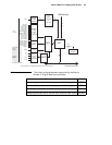
Lookup table (LUT)
Matrox Meteor-II /Multi-Channel has three 256x8-bit input
lookup tables (LUTs), allowing independent re-mapping of
three 8-bit input streams.
The LUTs on the Matrox Meteor-II /Multi-Channel for PCI
support RGB 8:8:8 (24-bit) output pixel formats. The LUTs on
the PC/104-Plus form factor support RGB 8:8:8, RGB 5:6:5, and
RGB 5:5:5 output pixel formats. LUTs are programmed using
the MIL-Lite command, MdigLut().
User bits
Meteor-II /Multi-Channel supports four auxiliary TTL user bits
through the video input connector: two input and two output.
These are available for controlling external events such as a
strobe light or PLC. User bits are programmed using the
MIL-Lite command MdigControl().