


40 Chapter 2: Hardware installation
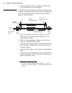
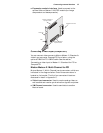
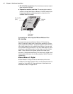
■ PC/104 (ISA) connectors. Two interface connectors to send
data across the ISA bus.
■ Expansion module interface. Three connectors used to
attach to the optional Matrox Meteor-II MJPEG module (for
image compression and decompression); located on the
soldered side of the board.
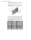
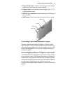
Connecting a video input to Matrox Meteor-II for
PC/104-Plus
Connect video sources to Matrox Meteor-II /Standard or
/Multi-Channel through their video input connector, a 30-pin
right-angle male connector. A standard cable for PC/104-Plus
form factor boards is not available from Matrox. You can use
the included mating connector, crimp the ribbon cable to it and
attach your required connector to the other end of the ribbon
cable. Then, connect this custom cable to the video input
connector. See Appendices B and C for the pinouts, signals, and
ribbon cable information for the /Standard and /Multi-Channel,
respectively.
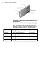
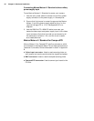
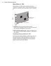
Matrox Meteor-II /Digital
Matrox Meteor-II /Digital has four connectors, which are
indicated in the diagram below. Only one of these connectors is
located on its bracket. All these connectors listed below are
discussed in detail in Appendix D.
PC/104-
(PCI)
Plus
PC/104
(ISA)
Video input
connector
Expansion
module
connectors