


Connecting external devices 39
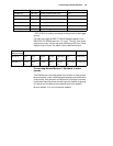
*OPTOTRIG- is usually connected to the ground of the trigger
source.
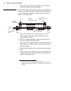
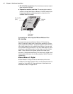
Connecting Matrox Meteor-II /Multi-Channel to other
boards
The VMChannel interface allows the transfer of data to other
Matrox boards. Insert a VMChannel backplane (available with
interconnect kits) across the VMChannel interface to connect
the boards. Note that when connecting multiple Matrox boards,
at least one of the boards you are connecting must be
bus-controller capable. Matrox Meteor-II is not bus-controller
capable.
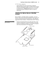
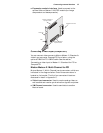
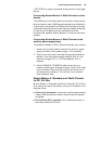
Connecting Matrox Meteor-II /Multi-Channel to the
auxiliary power supply input
To use Matrox Meteor-II /Multi-Channel to power your camera:
1. Use the 4-pin power cable to connect the auxiliary power
supply connector to the power supply in the computer.
2. Ensure that the jumper is across the appropriate Matrox
Meteor-II auxiliary power supply selection pins, for the
required voltage (5 V or 12 V). See Appendix B for a
diagram.
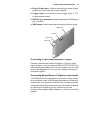
3. Use the DBHD44-TO-8BNC/O cable to connect your
camera’s video output and power supply input to the video
input connector. Note that the total current drawn by all
the cameras is limited to 1.5 A, and the circuit uses an
auto-resettable fuse.
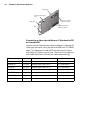
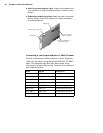
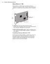
Matrox Meteor-II /Standard and /Multi-Channel
for PC/104-Plus
Matrox Meteor-II /Standard and /Multi-Channel PC/104-Plus
form factor have seven connectors, which are indicated in the
diagram below.
■ Video input connector. A connector used to receive analog
video, as well as send and receive synchronization signals
and power.
■ PC/104-Plus (PCI) connector. An interface connector to
send data across the PCI bus.