


Connecting external devices 35
*OPTOTRIG- is usually connected to the ground of the trigger
source.
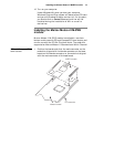
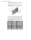
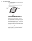
Connect the supplied BNC-TO SVHS adaptor cables to the
DBHD44-TO-13BNC cable for Y/C input. The PCI form factor
supports up to six Y/C sources, and the CompactPCI form factor
supports up to three. The cable is color coded as follows:
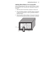
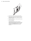
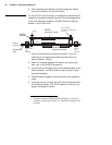
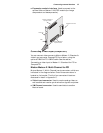
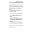
Connecting Matrox Meteor-II /Standard to other
boards
The VMChannel interface allows the transfer of data to other
Matrox boards. Insert a VMChannel backplane (available with
interconnect kits) across the VMChannel interface to connect
the boards. Note that when connecting multiple Matrox boards,
at least one of the boards must be bus-controller capable.
Matrox Meteor-II is not bus-master capable.
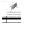
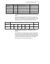
BROWN (8) VID_IN8 Analog Video Input8 or Y4 PCI
LIGHT BLUE (9) VID_IN9 Analog Video Input9 or Y5 PCI
ORANGE (10) VID_IN10 Analog Video Input10 or C5 PCI
PINK (11) VID_IN11 Analog Video Input11or Y6 PCI
LIGHT GREEN (12) VID_IN12 Analog Video Input12 or C6 PCI
GRAY (13) OPTOTRIG External trigger input* PCI, CompactPCI
Wires Signals Expected Input Form factor
Wires on
BNC-TO-SVHS
Wires on DBHD44-TO-13BNC Description
BLUE (Y) Red
(1)
Blue
(3)
Yellow
(6)
Brown
(8)
Light Blue
(9)
Pink
(11)
Luminance
GREEN (C) Green
(2)
Black
(4)
Purple
(7)
White
(5)
Orange
(10)
Light Green
(12)
Chrominance