


Installing Matrox Meteor-II 29
Installing Matrox Meteor-II for PC/104-Plus
Use the following steps to install your Matrox Meteor-II board
for PC/104-Plus:
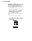
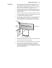
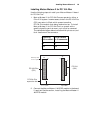
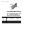
1. Matrox Meteor-II for PC/104-Plus can operate in either a
5V or 3.3V system. In some cases, a hole in the PC/104-Plus
(PCI) connector is filled, which prevents another
PC/104-Plus module from being stacked on top. To install
Matrox Meteor-II for PC/104-Plus in a system with a
specific signalling environment, a pin must be removed.
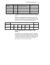
The table and diagram below indicate which pins to cut, and
their locations on the connector.
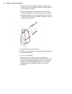
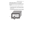
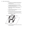
2. Connect the Matrox Meteor-II MJPEG module to the board
if required. See the section, Installing the Matrox Meteor-II
MJPEG module.
Signalling
environment
Pin to remove
on J3 connector
5V A1
3.3V D30
PC/104
(ISA)
Top view
PC/104-
expansion site
Plus
PC/104-
(PCI)
Plus
J3
J1
DCBA
BA
1
1
30
32
J2
CD
0
19
Remove pinA1
ina5Vsystem
Remove pin D30
in a 3.3 V system