


Operator's guide
source (which may have its own GPS unit, or take signals from one of the radio
time standards). The DCM can recognise GCF timing packets and will pass
them on to all connected digitizers.
GPS Power Cycle : If you have selected Garmin GPS as the timing source,
above, this setting determines how often the attached instrument will power up
the GPS receiver to obtain an accurate timing signal. Between timing fixes the
instrument will run on its internal clock, saving power at a small expense in
accuracy. If your instrument has ready access to a power source, you should
select always on.
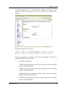
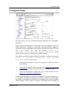
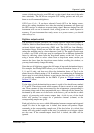
Digitizer output control
The analogue-to-digital converters on a Güralp digitizer output data sampled at
2000 Hz, which is then filtered and reduced to a lower rate (decimated) using an
on-board digital signal processing (DSP) unit. The DSP has four filtering-
decimation stages, which run one after the other. Each can be programmed to
reduce the sampling rate by a factor between 1 and 10. The output of each stage
is called a tap. Each of the taps may be configured for a different decimation
factor by choosing values from the drop-down menus on the left. If you are
using a mouse wheel to select values from a drop-down menu, ensure you
remove the focus from the drop-down menu before scrolling the window, or
you may inadvertently change the setting.
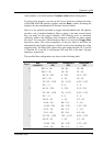
Note that not all digitizers support the full range of taps and decimation factors.
For example, the Güralp DM24 allows you to select decimation factors of 2, 4,
5, 8, and 10 only, and does not allow the decimation factor of Tap 0 to be
altered from its default setting of 10. In addition, no combination of decimation
factors may be used which produces a non-integer data rate (in Hz). A full list
of possible tap combinations for the DM24 is given in “Trigger criteria” in
Section 5.2, below.
To the right of each decimation factor menu is a grid of six check-boxes marked
Z, N, and E. These boxes mark which streams of data to record at each sample
rate. Three streams of data are measured by the seismometer, corresponding to
movement along each of three perpendicular axes. Although all the streams are
decimated by the same set of successive scale factors, you can decide at which
stage(s) of processing each stream outputs data. A tick in one of the check
boxes will produce an output for a particular channel (column) at the
corresponding sample rate (grid).
Each grid also has two rows, which differentiate between constant and triggered
output. If a box in the upper row is ticked, that stream will produce output
constantly at the corresponding sample rate. If the box below it is ticked, that
stream will only produce output at that rate if a particular set of trigger criteria
are also met. If the constant-output check box is ticked, the other will be
ignored.
December 2005 69