16
8170 N/B MAINTENANCE
@ Microphone In
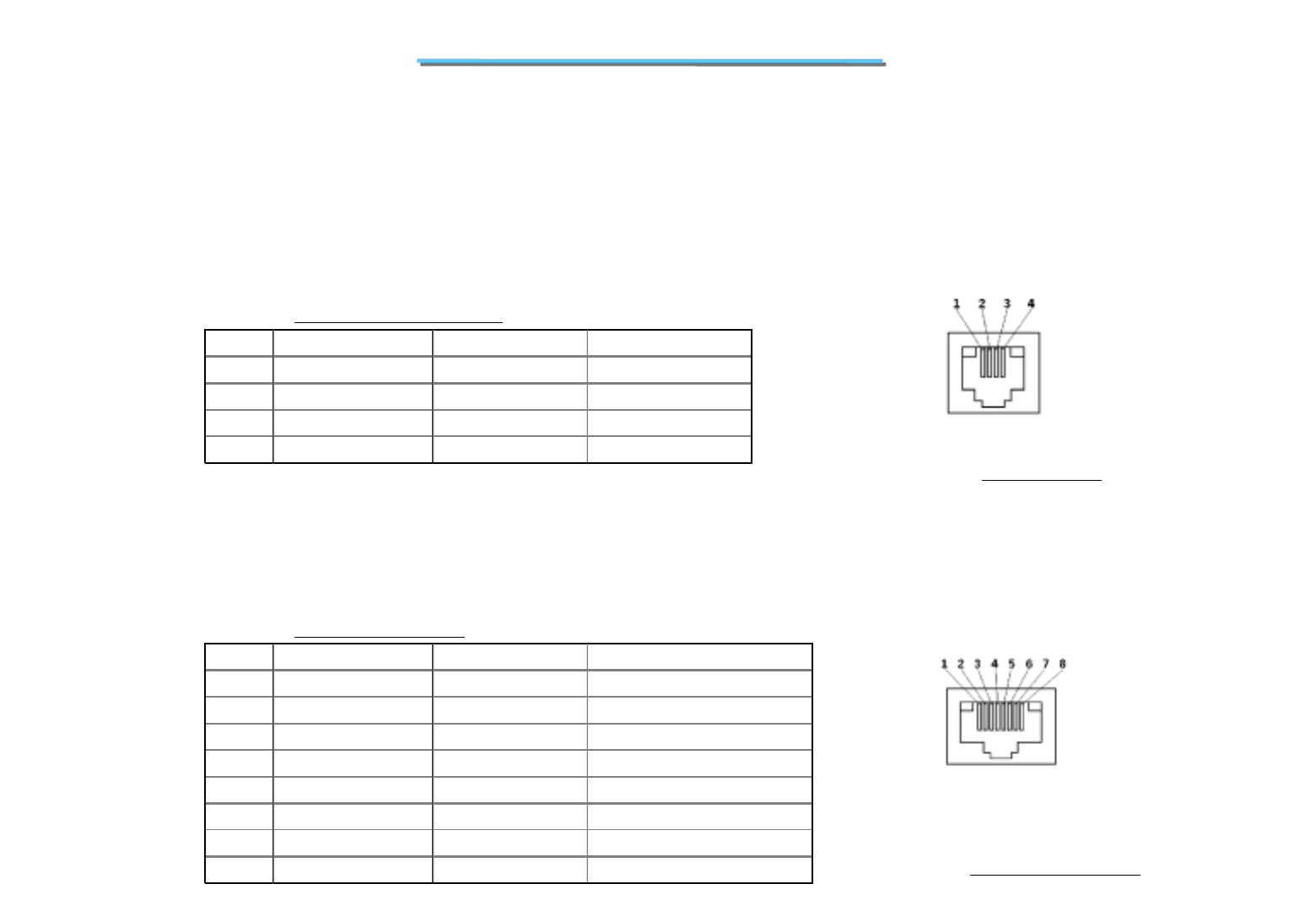
• RJ11
@ Connection to Modem Daughter Board connector
Table 1.5 MODEM CONNECTOR
Figure 1.5 MODEM Port
• RJ45
@ Connection to on-board NIC controller
Table 1.6 LAN CONNECTOR
Figure 1.6 LAN CONNECTOR
@ SPDIF
PIN SIGNAL NAME DIRECTION DESCRIPTION
1 NC - No Connect
2 LINE+ I/O Phone Line Positive
3 LINE- I/O Phone Line Negative
4 NC - No Connect
PIN SIGNAL NAME DIRECTION DESCRIPTION
1 TX+ Out Transmit Data Ring
2 TX- Out Transmit Data Tip
3 RX+ IN Receive Data Ring
4 TERM 1 - Internal termination resistor
5 TEMR 2 - Internal termination resistor
6RX IN Receive Data Tip
7 TERM 3 - Internal termination resistor
8 TERM 4 - Internal termination resistor


