


8
TROUBLESHOOTING
8.1 Troubleshooting Flowchart
8 - 2
1
OVERVIEW
2
SYSTEM
CONFIGURATION
3
SPECIFICATIONS
4
FUNCTIONS
5
PREPARATORY
PROCEDURES BEFORE
OPERATION
6
LINK DATA SEND/
RECEIVE PROCESSING
AND PROCESSING TIME
7
PROGRAMMING
8
TROUBLESHOOTING
8.1 Troubleshooting Flowchart
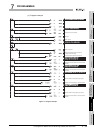
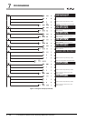
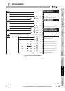
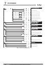
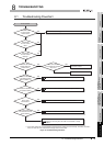
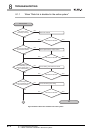
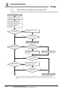
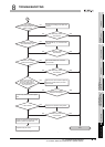
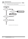
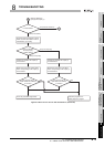
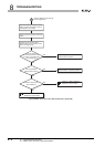
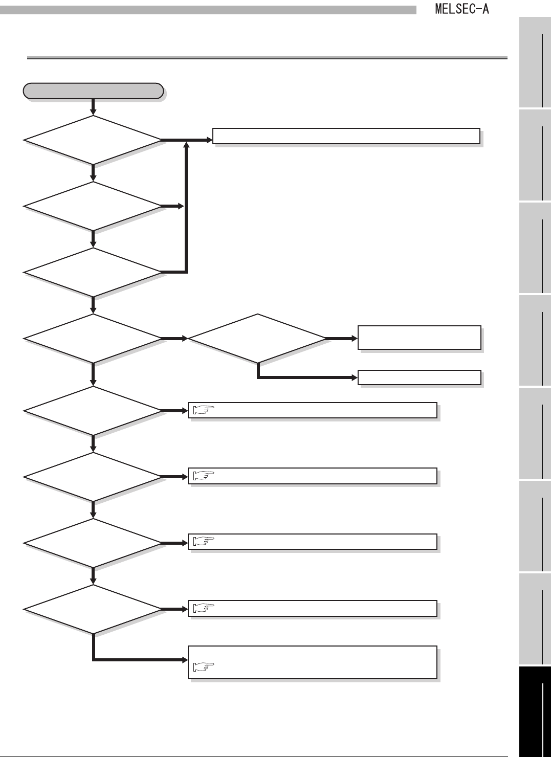
Figure 8.1 Troubleshooting Flowchart
YES
YES
YES
YES
Refer to troubleshooting section in CPU module manual.
YES
Modify sequence program, and
reset CPU module.
Replace link module hardware.
Error occurred.
NO
YES
NO
YES
NO
YES
*1
*1
NO
YES
Has CPU module
encountered an operation
stop error?
NO
NO
NO
NO
NO
Is data link disabled
at a specific station?
Error in data
transmission?
Is communication
error detected in some
slave stations?
Is POWER LED
on power supply
module OFF?
Is RUN LED
on CPU module
OFF?
Is RUN LED
on CPU module
flashing?
Is RUN LED on
master station link
module OFF?
Is data link disabled
in the entire system?
(Data in D9204 = 5)
Check if ERROR LED on link module is ON.
*1 If the mode, station No. or communication speed of the link module is not set correctly, "SP.UNIT LAY ERR."
will occur when the CPU module status changes from STOP to RUN.
Section 8.1.1 When "Data link is disabled in the entire system"
Section 8.1.2 When "Data link is disabled at a specific station"
Section 8.1.3 When "Error is found in data transmission"
Section 8.1.4 When "Communication error is detected in some
Section 8.3 Checking Error with LEDs of Link Module on Faulty
Station