


3 - 25
3.6 Details of Buffer Memory
3.6.5 LWTP instruction receive request/receive result/work area
3
SPECIFICATIONS
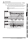
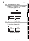
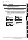
(1) LWTP instruction receive request (Buffer memory address: AEH)
The receive request for the LWTP instruction is stored.
4: Processing requested (System sets it when LWTP instruction is accepted.)
5: Processing completed (User has to set it after the write data is stored.)
Other than the above: No request
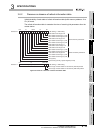
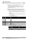
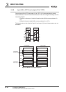
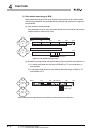
(2) LWTP instruction work area (Buffer memory address: D8H to FFH)
When the LWTP instruction receive request (buffer memory address: AEH) is "4", the
requested content of the LWTP instruction is stored into the following area.)
1) Write the write data of a local module to the device of the CPU module (buffer
memory address: DC
H to FFH) using the following area in a sequence
program.
2) After writing data, set "5" to the LWTP instruction receive request (buffer
memory address: AE
H).
3) The processing completion is notified to the master station.
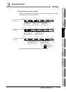
* 1 Stored value when start device is D100
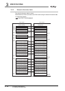
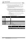
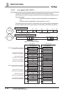
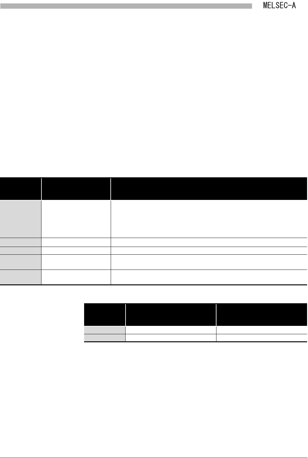
Table 3.14 LWTP instruction work area
Address
Hexadecimal
(Decimal)
Item Description
D8H(216)
Write start device name
*1
Stores a start device name (device code) of the CPU module.
544E
H: T
434E
H: C
4420
H: D
5720
H: W
D9H(217)
Write start device No.
*1
Stores a start device No. of the CPU module.
DAH(218) System area (Use prohibited) -
DBH(219) Write data length
Stores the number of write data.
1 to 32 (Word)
DCH to FFH
(220 to 255)
Write data Stores the write data.
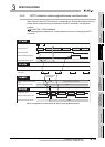
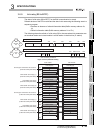
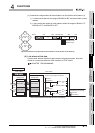
Table 3.15 Stored value when start device is D100
Address
Hexadecimal
(Decimal)
Item (description) Stored value
D8H(216) Write start device name (D) 4420H
D9H(217) Write start device No.(100) 0064H