


APPENDICES
Appendix 5 Program for Refresh when Using Multiple Local Modules
Appendix 5.2 Program for refresh
App - 17
APPENDICESINDEX
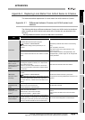
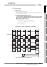
(3) Program examples
(a) Program overview
1) Refresh range of local station No.4
All areas are refreshed according to the refresh information table (Buffer
memory address: 2
H to 27H).
2) Refresh range of local stations No.5 to No.7
The areas of the host station send ranges in B/W and Y and the host station
receive range in X are refreshed according to the refresh information table
(Buffer memory address: 2
H to 27H).
The following areas are not refreshed.
• Other station send range (1) and (2) in B/W
• Send range of master station for second tier in B/W
• Special relay (for link)
• Special register (for link)
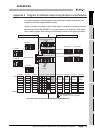
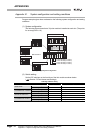
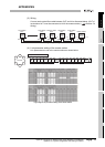
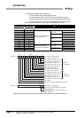
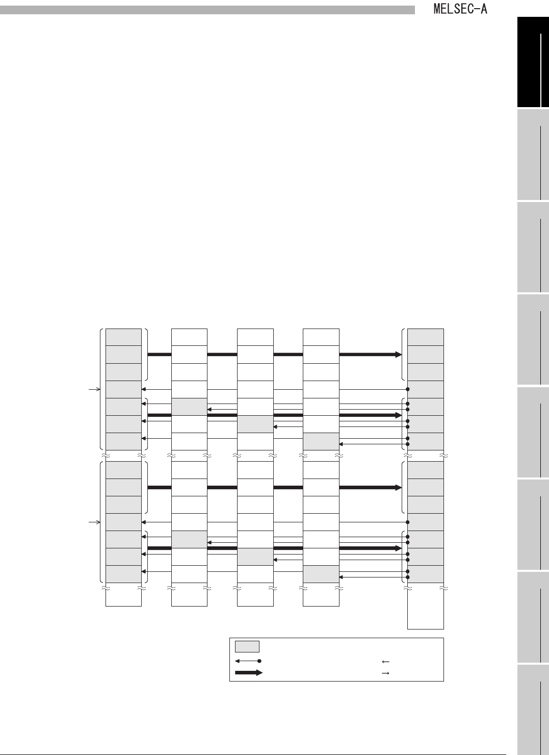
An example of link register (W) data transfer is shown below.
Figure App.6 Example of link register (W) data transfer
W0
CPU module
Link register (W)
Local station No.4
buffer memory
Local station No.5
buffer memory
Local station No.6
buffer memory
Local station No.7
buffer memory
W0
First half of
link parameters
M station
L1 station
L2 station
L4 station
L5 station
L6 station
L7 station
M station
L1 station
L2 station
L4 station
L5 station
L6 station
L7 station
M station
L1 station
L2 station
L4 station
L5 station
L6 station
L7 station
M station
L1 station
L2 station
L4 station
L5 station
L6 station
L7 station
M station
L1 station
L2 station
L4 station
L5 station
L6 station
L7 station
M station
L1 station
L2 station
L4 station
L5 station
L6 station
L7 station
M station
L1 station
L2 station
L4 station
L5 station
L6 station
L7 station
M station
L1 station
L2 station
L4 station
L5 station
L6 station
L7 station
M station
L1 station
L2 station
L4 station
L5 station
L6 station
L7 station
M station
L1 station
L2 station
L4 station
L5 station
L6 station
L7 station
Latter half of
link parameters
WFFF WFFF
W1FFF
Refresh range
Transfer direction (Local module CPU module)
Transfer direction (Local module CPU module)