


3 - 13
3.4 I/O Signal for Programmable Controller CPU
3.4.2 Details of I/O signal
3
SPECIFICATIONS
3.4.2 Details of I/O signal
The following shows details of I/O signal of a local module.
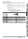
(1) Link status (X0)
The link status is turned ON when the host station is offline, station-to-station test, or
self-loopback test.
The link status is turned OFF when setting the host station online and turning power
supply ON from OFF or resetting the CPU module.
(2) B/W initial value setting status (X1), Refresh ready status (X7), CPU
operating status (Y10), Refresh in execution (Y11), and Refresh request
(Y16)
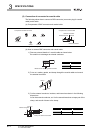
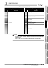
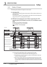
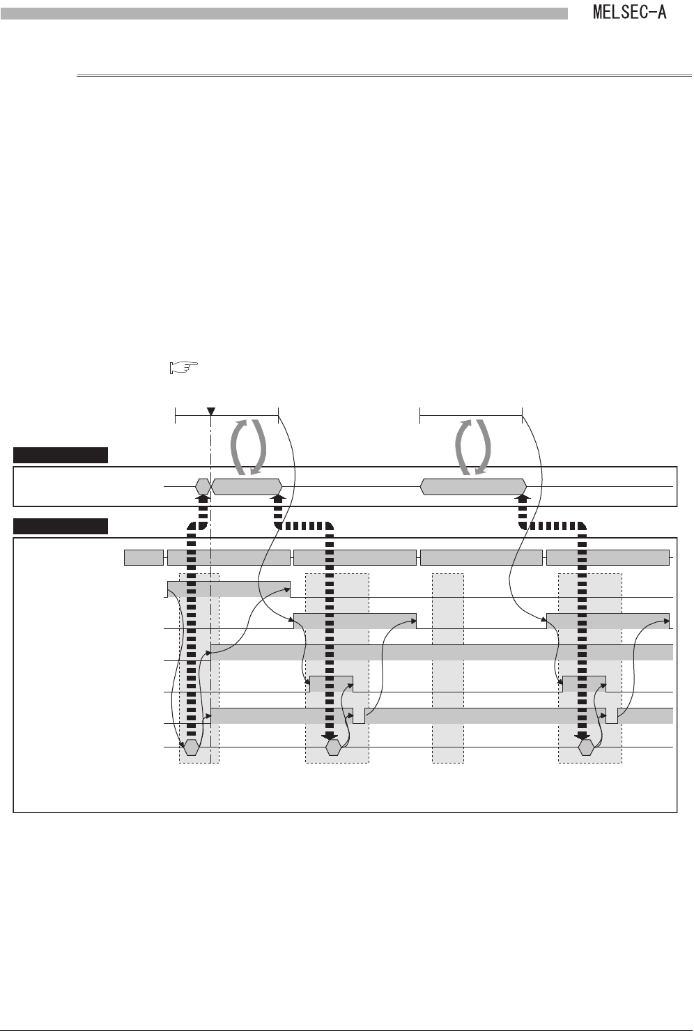
Operations of link refresh are shown below.
For the programming, refer to the following.
CHAPTER 7 PROGRAMMING
(a) Turning power supply ON from OFF or resetting the CPU module
1) A local module turns ON the B/W initial value setting status (X1).
2) The B/W device of the CPU module is written to the B/W device of the local
module in a sequence program.
3) When CPU operating status (DY10) and Refresh request (DY16) are turned
ON in a sequence program after writing the initial value to the B/W device of
the local module, a Q series local station starts data communication with other
stations.
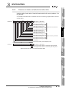
Figure 3.4 Operation of link refresh
Link scan
Refresh in execution (DY11)
Refresh ready status (X7)
Device memory storage area
Local moduleLocal module
Link data storage area
CPU moduleCPU module
Sequence scan
Power-on
CPU operating status (DY10)
B/W initial value setting status (X1)
Refresh request (DY16)
Sending/receiving data
Sending/receiving data
At power-on, sending/receiving
data to/from other station is started
after setting the B/W initial value.
0 END 0 END0END
(Buffer memory address: 100H to 13FFH)
Program for refresh
0END