


4
FUNCTIONS
4.1 Cyclic Transmission Function
4.1.1 1 : n communication (B/W communication)
4 - 3
1
OVERVIEW
2
SYSTEM
CONFIGURATION
3
SPECIFICATIONS
4
FUNCTIONS
5
PREPARATORY
PROCEDURES BEFORE
OPERATION
6
LINK DATA SEND/
RECEIVE PROCESSING
AND PROCESSING TIME
7
PROGRAMMING
8
TROUBLESHOOTING
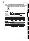
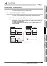
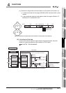
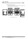
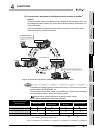
(c) Send/receive ranges when the local module is on the third-tier local station (l1)
1) l1 station writes data into the range of B/W280 to 2BF, and sends them to other
stations.
2) It can receive data written by other stations within the ranges of B/W0 to FF,
B/W200 to 27F, and B/W2C0 to 2FF.
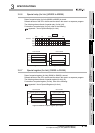
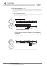
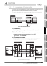
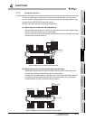
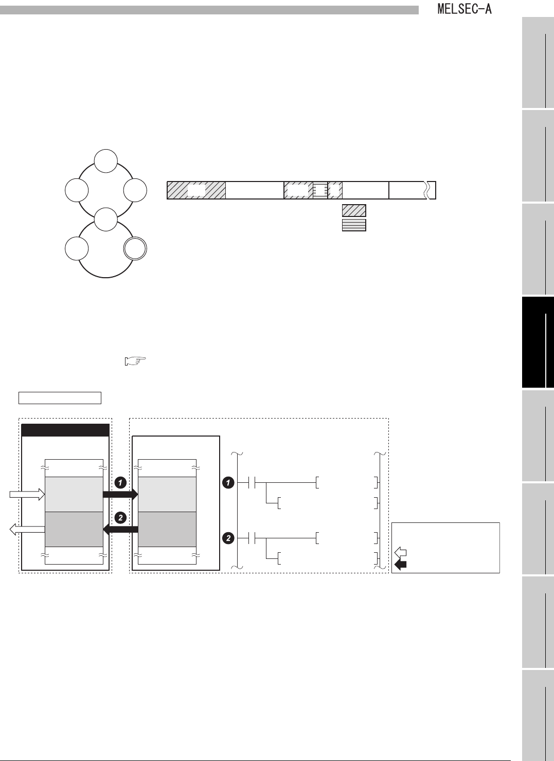
(2) Link refresh of link data
Q series local stations refresh link data using the sequence program. Note that
refresh is not executed when the CPU module is in STOP status.
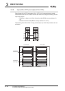
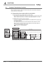
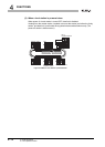
CHAPTER 7 PROGRAMMING
Figure 4.4 Send/receive ranges when the local module is on the third-tier local station (l1)
Figure 4.5 Link refresh of link data (Q series local station)
100 200 300 380
(Empty)
FFF280 2C0
L3
Second
tier
l2
Third
tier
L2/m
ML1L2/ml2L3
Readable range
Writable range
M
l1
L1
l1
B/W 0
Q series local station
Local module CPU module
Link data
storage area
Buffer memory
Buffer memory
Data memory
storage area
Link scan
Link refresh
Data flow
(Send/receive processing)
400
H
4FFH
500H
5FFH
Receive
processing
DMOV Z0
BMOV W0Z0 Z1
Send
processing
W0 to WFF
W100 to W1FF
"A part" of the program for refresh
U0\
G4
U0\
G1024Z0
DMOV Z0
U0\
G2
BMOV W0Z0 Z1
U0\
G1024Z0
W0 to WFF
W100 to W1FF