


4 - 2
4.1 Cyclic Transmission Function
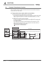
4.1.1 1 : n communication (B/W communication)
4
FUNCTIONS
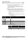
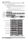
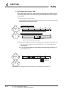
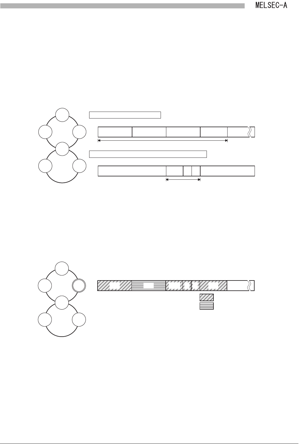
(1) Each station send range in B/W
Each station send range in B/W is set up with link parameters of the master station.
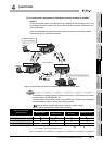
The following explains a link parameter setting example and send/receive ranges for
local modules.
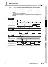
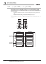
(a) Link parameter setting example
Link parameters must be set to the master station for the second tier (M) and the
master station for the third tier (L2/m).
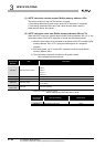
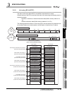
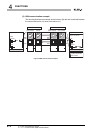
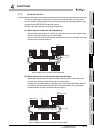
(b) Send/receive ranges when the local module is on the second-tier local station (L1)
1) L1 station writes data into the range of B/W100 to 1FF, and sends them to
other stations.
2) It can receive data written by other stations within the ranges of B/W0 to FF
and B/W200 to 37F.
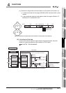
Figure 4.2 Link parameter setting example
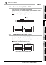
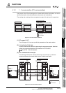
Figure 4.3 Send/receive ranges when the local module is on the second-tier local station (L1)
First half of link parameters
M
L1
100 200
L2/m
300 380
L3
(Empty)
FFF
200
L2/m
300
l1
280
l2
2C0
First half of link parameters
M
L1L3
Second
tier
l1l2
Third
tier
L2/m
B/W 0
FFFB/W 0
Link parameters for second tier
Link parameters of master station for third tier (L2/m)
100 200 300 380
(Empty)
FFF280 2C0
L1L3
Second
tier
l1l2
Third
tier
L2/m
ML1L2/ml1l2L3
Readable range
Writable range
M
B/W 0