


7 - 1
7.1 System Configuration and Setting Conditions
7
PROGRAMMING
CHAPTER7 PROGRAMMING
This chapter describes a program for refreshing the local module and for receiving
LRDP/LWTP instruction.
7.1 System Configuration and Setting Conditions
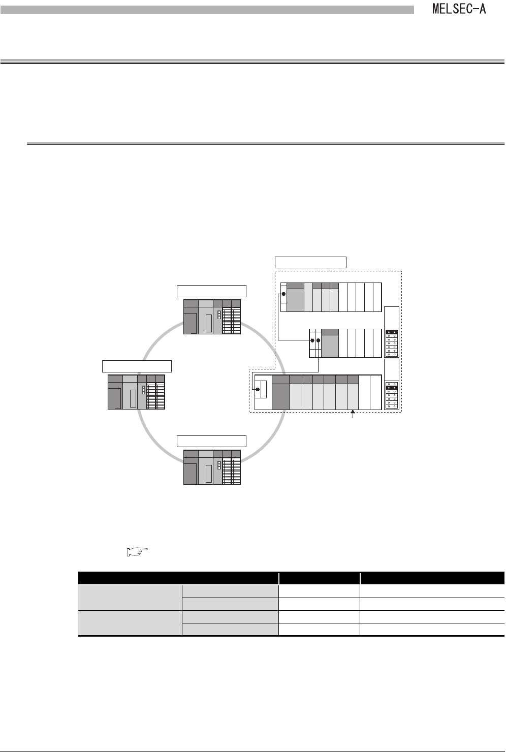
Program examples given here are based on the following system configuration and setting
conditions.
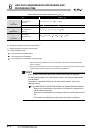
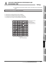
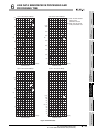
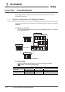
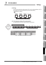
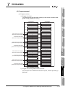
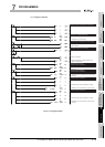
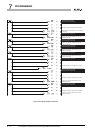
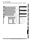
(1) System configuration
The following figure shows that a 32-point module is installed to each slot. (The points
for an empty slot is 16.)
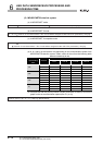
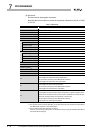
(2) Switch setting
Set the DIP switches on the front face of the link module as shown below.
( Section 5.3 Part Names and Settings)
Figure 7.1 System configuration
Table 7.1 Switch setting
Item Number (Set value) Description
Master station
Station No. setting switch 00 Station No.0
Mode setting switch 0 Online (with automatic return function)
Local stations No.1 to No.3
Station No. setting switch 01 to 03 Station No.1 to No.3
Mode setting switch 0 Online (with automatic return function)
MELSECNET II
(Q38B)
A1SJ71AP23Q
Master station
Local station No.1
Local station No.2
Local station No.3
00 to 1F
100 to 11F
120 to 13F
140 to 15F
160 to 17F
180 to 19F
200 to 21F
220 to 22F
230 to 23F
20 to 3F
40 to 5F
60 to 6F
70 to 7F
80 to 8F
90 to 9F
A0 to AF
B0 to BF
C0 to CF
D0 to DF
E0 to EF
F0 to FF
(Q65B)
(QA1S68B)
Extension
1st
Extension
2nd