


6 - 17 6 - 17
MELSEC-Q
6 DATA COMMUNICATION USING THE NON PROCEDURE PROTOCOL
6.1.5 How to detect reception errors
This section explains how to detect errors that may occur when receiving data from the
external device.
The following items are considered as the primary causes of errors that may occur
during data reception.
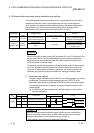
Cause of reception error Reference section
A transmission error occurred due to noise. —
A timeout for the no-reception monitoring (timer 0) occurred. Chapter 6
Received data that could not be converted using the ASCII-BIN conversion.
User's Manual
(Application)
Chapter 13
Received data larger than the size that could be stored in the OS area of the Q series C24. Section 6.1.2
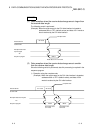
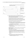
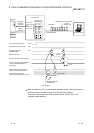
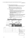
(1) Confirmation using the sequence program
1) The following device and input signals turn ON.
• INPUT instruction complete device + 1
• Reception abnormal detection signal (X4/XB)
• ERR LED ON signal (XE/XF)
2) The reception error code can be checked using the INPUT instruction
control data ((S1) + 1).
Or, it can be checked by reading the data reception result storage area
in the buffer memory (addresses 258
H
/268
H
).
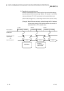
For details on how to check the error code contents and take corrective
actions, see Chapter 10.
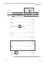
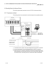
(b) How to turn off the ERR LED and clear the error code (see Section 10.1.2.)
1) To turn off only the ERR LED, write "1" to the LED OFF request area
(addresses 0
H
/1
H
) in the buffer memory.
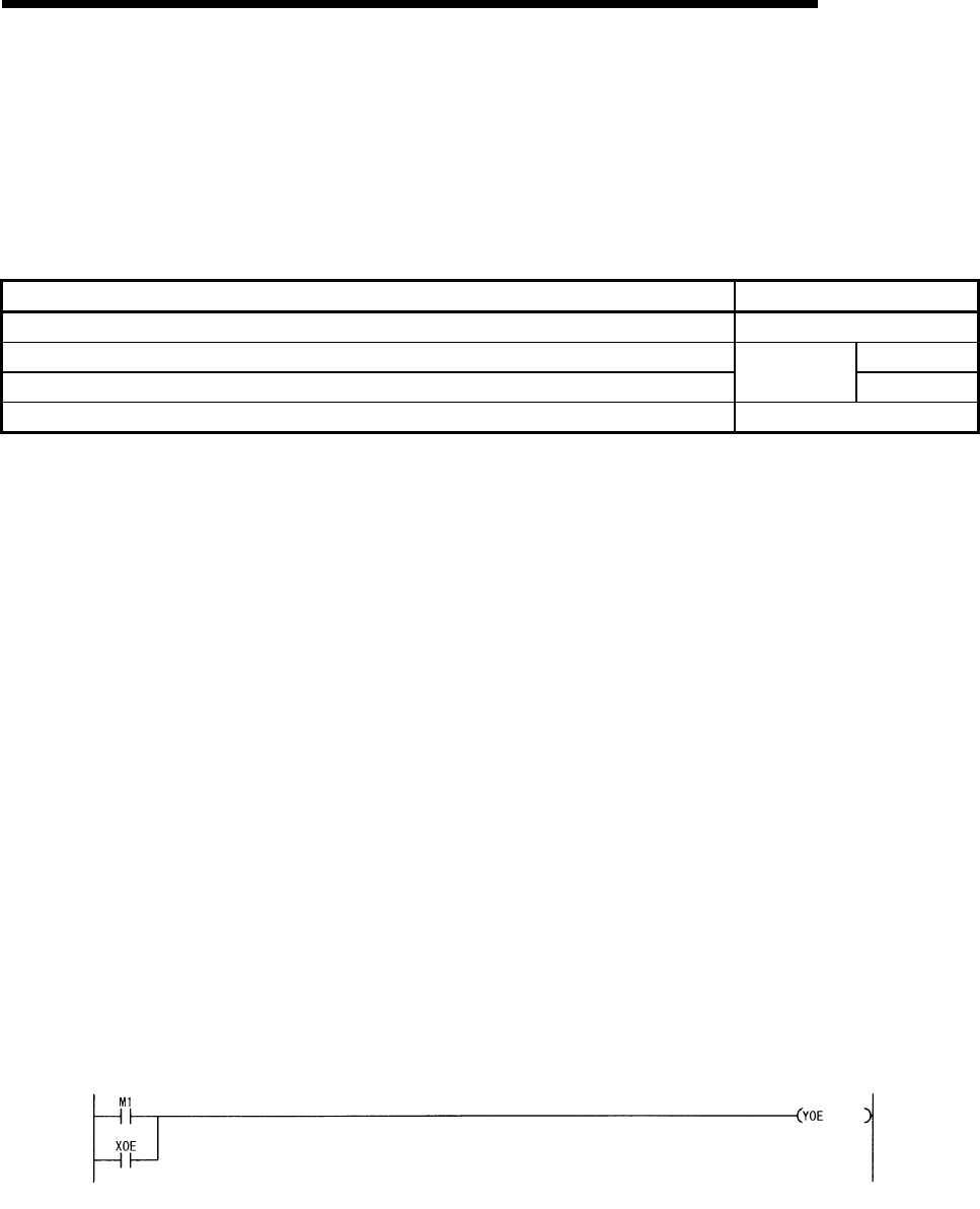
2) To turn off the ERR LED and clear the error code, turn ON the ERR LED
OFF request output signal (YE/YF).
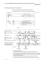
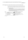
(Example) To perform the ERR LED OFF and the error code clear on the
CH1 side
INPUT instruction
Completion device + 1