


3 - 16 3 - 16
MELSEC-Q
3 SPECIFICATIONS
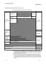
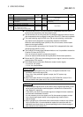
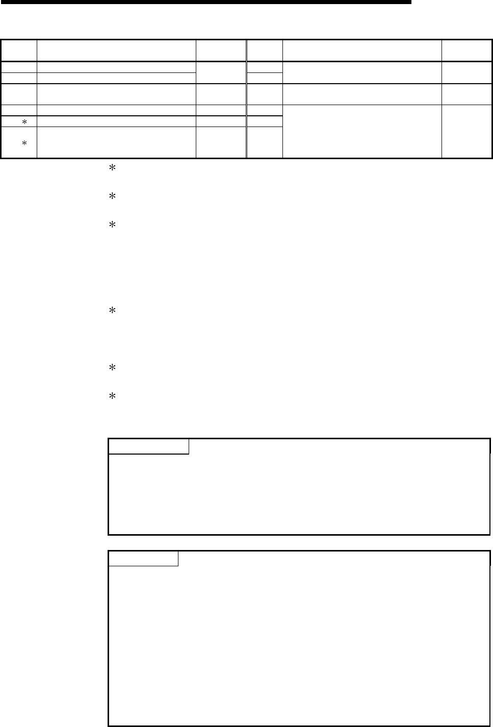
Device
number
Signal description
Reference
section
Device
number
Signal description
Reference
section
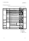
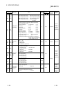
X1A CH1 Global signal ON: Output instructed Y1A
X1B CH2 Global signal ON: Output instructed
Section 3.10,
Reference
Y1B
Use prohibited —
X1C
System setting default completion
ON: Completed
Section 8.4.11 Y1C
System setting default request
ON: Requesting
Section 8.4.11
X1D (For system) — Y1D
X1E 4 Q series C24 ready ON: Accessible — Y1E
X1F 5
Watchdog timer error (WDT error)
ON : Module error occurred
OFF: Module being normally operated
—Y1F
Use prohibited —
1 The device does not turn on/off by execution of a dedicated instruction when a
function that corresponds to the input signal is used.
2 The device does turn on/off by execution of a dedicated instruction when a function
that corresponds to the input signal is used (from ON to OFF: Data read completed).
3 The mode switching signal (X6/XD) turns ON at mode switching, receive clear,
user frame receive designation or transmission sequence initialization.
While the mode switching signal (X6/XD) is ON, do not issue a communication
request to the target interface.
(The communication processing of the Q series C24 is stopped while the mode
switching signal (X6/XD) is ON.)
4 The Q series C24 ready signal indicates whether or not it is possible to access the
Q series C24 from the PLC CPU.
Use it as a interlock signal for a sequence program.
(It turns on about one second after turning the power ON and reset operation.)
5 Restart the PLC CPU when the watchdog timer error signal is turned on (reset the
power and the CPU module).
6 QJ71C24N-R4 cannot be used. (Related to modem function signal.)
• X10 to X16: For system
• Y10 to Y16: Use prohibited
IMPORTANT
(1) Of the input/output signals to the PLC CPU, the signals marked with "Use
prohibited" must not be output (ON).
If any of the "Use prohibited" signals is output, the PLC system may
malfunction.
(2) When the modem function is not used or the QJ71C24N-R4 is used, X10 to
X16 are used for the system and Y10 to Y16 cannot be used.
POINT
(1) The input/output signals shown in this section are the signals used when a QnA
series serial communication module program is utilized for the Q series C24
(see Section 2 in appendix).
In the QCPU, the on/off of input/output signals to intelligent function modules is
executed with a dedicated instruction.
It is not necessary to turn the signals on/off by the sequence program, except
for the input/output signals shown in the programming of each function
reference page.
(2) When a program for a QnA series serial communication module is also utilized
for the Q series C24, it is recommended to replace the instructions with the
dedicated instructions shown on the corresponding function reference page of
each manual for the Q series C24.