4 - 16 4 - 16
MELSEC-Q
4 SETTINGS AND PROCEDURES PRIOR TO OPERATION
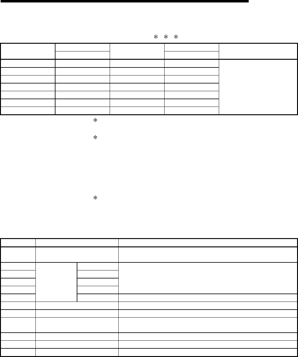
(b) Communication rate setting (CH1 side: switch 1 (upper level); CH2 side:
switch 3 (upper level))
1 2 3
Bit position Bit position
Communication rate
(Unit: bps)
b15 to b8
Communication rate
(Unit: bps)
b15 to b8
Remarks
50 0F
H
14400 06
H
300 00
H
19200 07
H
600 01
H
28800 08
H
1200 02
H
38400 09
H
2400 03
H
57600 0A
H
4800 04
H
115200 0B
H
9600 05
H
230400 0C
H
Try lowering the communication
rate when data cannot be
communicated normally with an
external device due to overrun
errors and framing errors etc.
1 Transmission speed of 230,400 bps is available for only CH1 of the
QJ71C24N (-R2/R4).
2 When connecting external devices to both of two interfaces, the total of
the communication speed should be 115,200bps or less (230,400 bps
or less if using QJ71C24N (-R2/R4)). When connecting an external
device to either of two interfaces, the maximum of 115,200 bps is
available for the interface (the maximum of 230,400 bps if using
QJ71C24N (-R2/R4)). In this case, set 300 bps for the other interface to
which no external device is connected.
3 Set "00
H
" to the interface for which "GX Developer connection" is set in
the communication protocol setting. Serial communication module will
operate at the communication speed set on the GX Developer.
(c) Communication protocol setting (CH1 side: switch 2; CH2 side: switch 4)
Set number Description Remarks
0
H
GX Developer connection
GX Developer communication rate and transmission specifications are
automatically set.
1
H
Format 1
2
H
Format 2
3
H
Format 3
4
H
Format 4
For communication with ASCII code in the specified form of an A compatible 1C
frame or QnA compatible 2C/3C/4C frame
5
H
MC protocol
Format 5 For communication with binary code in a QnA compatible 4C frame
6
H
Non procedure protocol For communication using non procedure protocol
7
H
Bidirectional protocol For communication using bidirectional protocol
8
H
For linked operation setting
Set to the CH1 side when CH1 and CH2 interfaces are used in linked operation
(operated with the communication protocol of the CH2 side).
9
H
to D
H
Setting prohibited —
E
H
ROM/RAM/switch test For self-diagnosis of the modules
F
H
Individual station loopback test For checking operation of each interface of the modules


