


4 - 3 4 - 3
MELSEC-Q
4 SETTINGS AND PROCEDURES PRIOR TO OPERATION
4.3 Part Names and Functions
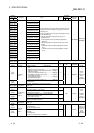
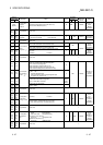
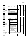
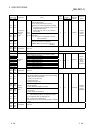
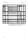
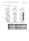
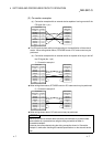
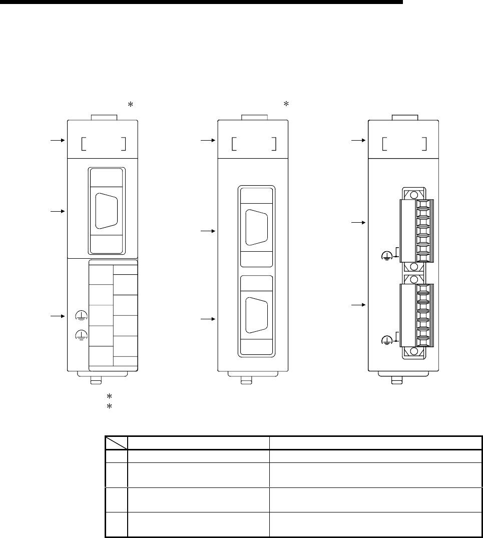
Part names of Q series C24 are shown below.
CH2
CH1
RS-422/485
RS-422/485
QJ71C24N-R4
(FG)
SG
RDB
RDA
SDB
SG
RDB
RDA
SDB
SDA
SDA
(FG)
QJ71C24N-R4
RUN
RD
NEU.
SD
NEU.
RD
SD
CH1
CH2
ERR.
1) 1) 1)
2
)
3)
2)
2)
4)
4)
( 1)
QJ71C24N-R2
RS-232
RS-232
CH2
CH1
QJ71C24N-R2
RUN
RD
NEU.
SD
NEU.
RD
SD
CH1
CH2
ERR.
4
2
5
3
1
6
7
(FG)
(FG)
RS-232
/485
RS-422
CH2
RDB
RDA
SDB
SG
SDA
CH1
QJ71C24N
RUN
RD
NEU.
SD
NEU.
RD
SD
CH1
CH2
ERR.
QJ71C24N
QJ71C24 ( 2)
QJ71C24N-R2
QJ71C24-R2
QJ71C24N-R4
1 The external diagrams of the QJ71C24 are the same as QJ71C24N (except for the model name).
2 The external diagrams of the QJ71C24-R2 are the same as QJ71C24N-R2 (except for the model
name).
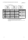
Name Contents
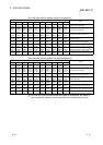
1) Display LED Display LED (For details, see (1).)
2) RS-232 interface
RS232 interface for serial communication with external
devices (D-Sub 9 pin)
3) RS-422/485 interface
RS422/485 interface for serial communication with external
devices (2-piece terminal block)
4) RS-422/485 interface
RS422/485 interface for serial communication with external
devices (2-piece plug-in socket block)