


4 - 6 4 - 6
MELSEC-Q
4 SETTINGS AND PROCEDURES PRIOR TO OPERATION
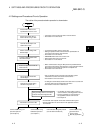
4.4.1 Connecting the RS-232 interface (full-duplex communications)
The following shows the connection precautions and connection examples when using
the Q series C24 RS-232 interface for full-duplex communications.
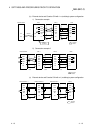
(1) Connection precautions
(a) For further information about the following items, see the explanation in the
applicable section in the User's Manual (Application).
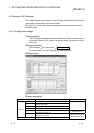
• Controlling the communication on the Q series C24 side by the external
device side using the CD signal of the RS-232 interface.
This is affected by the "RS-232 CD terminal check setting" in "CHn
transmission control and others system setting change" screen on GX
Configurator-SC.
• Performing half-duplex communication using specifications on the external
device side (an example of such a connection is shown in this section).
• Using modem functions.
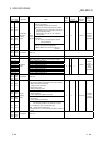
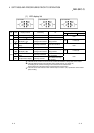
(b) The connection cable FG signal and shield are connected as follows.
Connection on the Q series C24 side Notes
Connection cable FG signal
Connect to the Q series C24 connector
housing
Connection cable shield
Connect to the external device FG terminal
or the Q series C24 connector housing
Do not short the communication cable FG
signal and the SG signal.
When the FG signal and the SG signal are
connected inside the external device, do not
connect the FG signal to the Q series C24.
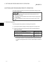
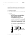
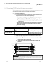
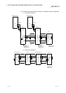
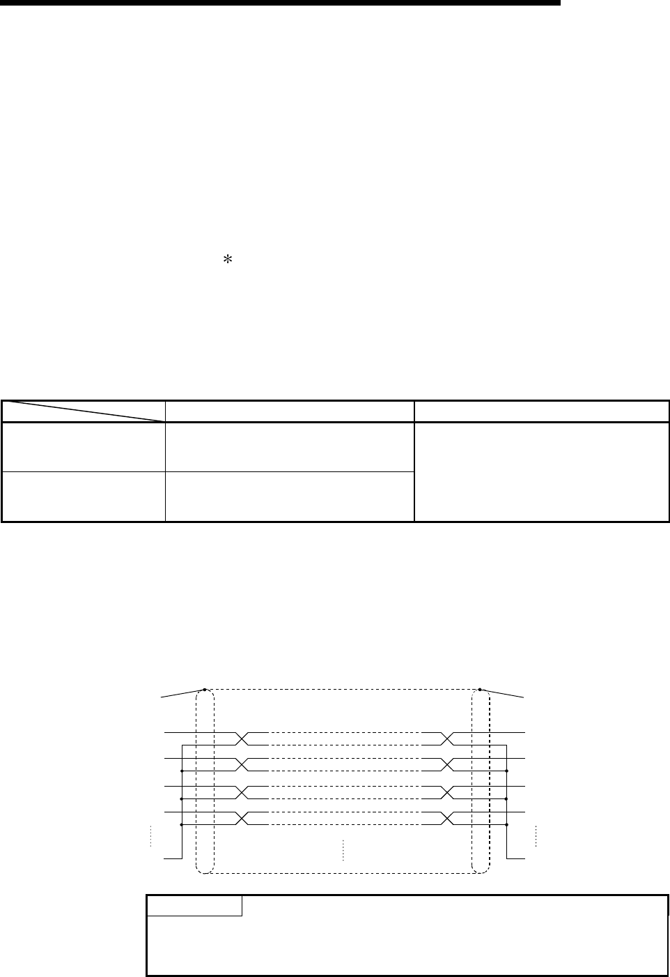
(c) When normal data communication is not obtained due to external noise,
perform the wiring as follows:
1) Connect the FG terminals on the external device and the Q series C24
using the shield of the connection cable.
2) Signals other than SG should be connected with SG signals in the
twisted pair.
FG
RD
SD
DTR
DSR
SG
RD
SD
DTR
DSR
SG
To Connector
housing
Q series C24
Shield
(External device)
POINT
When using an RS-232 to RS-422 converter to connect the external device and the
Q series C24, use a converter that is compatible with the external device and PLC
CPU system configuration (1:1).