


9 - 16 9 - 16
MELSEC-Q
9 DEDICATED INSTRUCTIONS
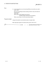
Error
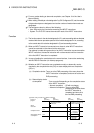
(1) In case of operation errors, the error flag (SM0) turns on and the error code is
stored in SD0.
See one of the following manuals according to the error code, and check and
correct the error.
<Error code>
4FFF
H
or less : QCPU(Q Mode) User's Manual
(Hardware Design, Maintenance and Inspection)
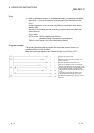
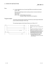
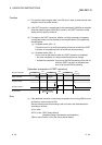
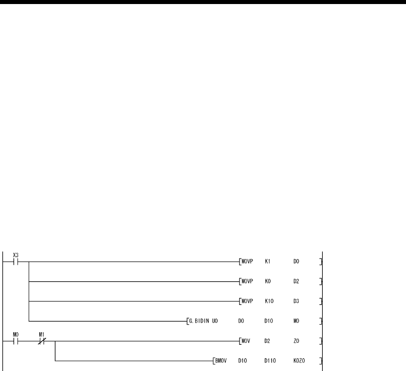
Program example
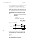
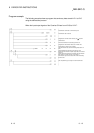
The following example shows a program that receives any data using the bidirectional
protocol and stores that data in D10 or later.
The input/output signals of the Q series C24 are from X/Y00 to X/Y1F:
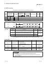
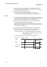
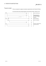
Clear the receive data count storage device
to 0.
Designate the allowable receive data count.
•
The reading of received data is performed
by the PLC CPU.
Designate the receive channel.
•
After the BIDIN instruction is executed,
the user designated read completion
signal (M0) comes on for 1 scan.
With the normal completion, the receive
data within the allowable receive data count
(user designated) is read from the receive
data storage area in the buffer memory.