


2 - 1 2 - 1
MELSEC-Q
2 SYSTEM CONFIGURATION AND AVAILABLE FUNCTIONS
2
2 SYSTEM CONFIGURATION AND AVAILABLE FUNCTIONS
This Chapter describes the system configuration and available functions.
2.1 Applicable Systems
The following describes applicable systems.
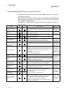
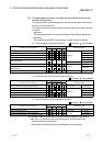
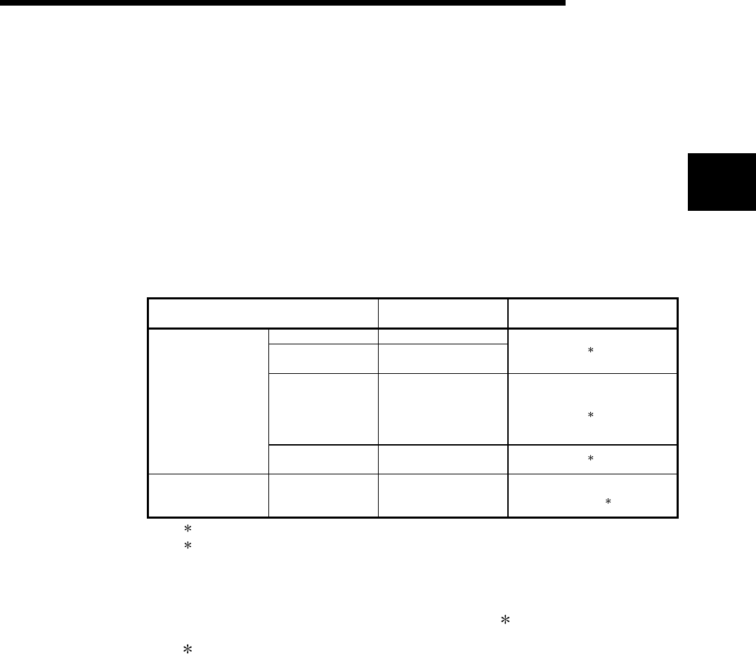
(1) Applicable modules and number of modules that can be mounted
The following table lists the CPU module and network modules (for remote I/O
stations) that the Q series C24 can be mounted and the number of modules
which can be mounted.
Applicable module
Number of modules that
can be installed
Remarks
Q00JCPU Maximum 8
Q00CPU
Q01CPU
Maximum 24
(
1
)
Q02CPU
Q02HCPU
Q06HCPU
Q12HCPU
Q25HCPU
Maximum 64
Can be installed in Q mode only
(
1
)
CPU module
Q12PHCPU
Q25PHCPU
Maximum 64
(
1
)
Network module
QJ72LP25-25
QJ71LP25GE
QJ72BR15
Maximum 64
MELSECNET/H Remote I/O
station (
2
)
1 See User's Manual (Function Explanation, Program Fundamentals) for the CPU module to use.
2 See Q Corresponding MELSECNET/H Network System Reference Manual (Remote I/O
network).
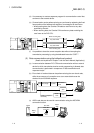
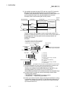
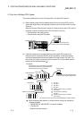
(2) The base module to which the Q series C24 can be mounted
The Q series C24 can be mounted into any I/O slot ( 1) of the base module.
1 Limited to within the range of I/O points for the CPU module and network
module (for remote I/O station)
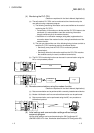
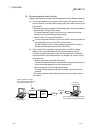
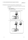
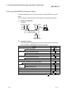
(3) Multiple CPU systems
When using the Q series C24 on a multiple CPU system, refer to the QPU User's
Manual (Multiple CPU System) before operation.
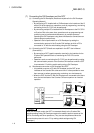
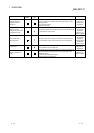
(a) Applicable Q series C24
If using the Q series C24 on a multiple CPU system, use function version B
of the Q series C24.
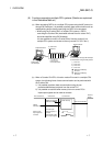
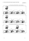
(b) Intelligent function module parameter
To write the intelligent function module parameter on a PLC, be sure to
write it in the Q series C24 control PLC only.