


Chapter 2 BridgeVIEW Environment
BridgeVIEW User Manual 2-10 © National Instruments Corporation
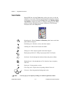
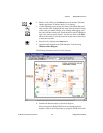
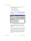
diagram as source code. The components of the block diagram
represent program nodes such as For Loops, Case structures, and
multiplication functions. The components are wired together to show
the flow of data within the block diagram.
The outermost structure in this diagram is the While Loop. It continues
to run until the power switch is turned off. The objects inside the loop
include functions and subVIs that generate simulated data that is
displayed on the historical trends and other objects on the front panel.
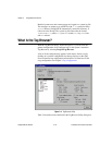
At this point, you do not need to understand all of the structures and
objects completely. Chapters 9 through 16 of this manual describe in
greater detail each element that appears in a VI.
7. Close the VI.
End of Activity 2-1.
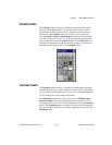
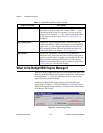
BridgeVIEW Environment Project Menu
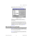
The BridgeVIEW system is comprised of the G programming language
and a collection of software tools designed specifically for industrial
automation applications. You can access these tools through the Project
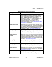
menu in your BridgeVIEW system. Table 2-1 provides a brief description
of the items in the Project menu.
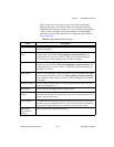
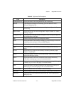
Table 2-1.
BridgeVIEW Project Menu Items
Project Menu Item Description
Configure BridgeVIEW
Startup
Opens a utility you can use to configure BridgeVIEW to start
particular VIs whenever you start BridgeVIEW.
Historical Trend Viewer Launches the Historical Trend Viewer (HTV). You can use the
HTV to view historical data logged in the Citadel Historical
Database. For more information about the HTV, see Chapter 6,
Historical Data Logging and Extraction.