


ND-70185 (E) CHAPTER 6
Page 135
Revision 3.0
POST INSTALLATION TEST
Repair Procedure When LED Indicates Abnormality
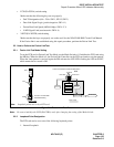
• FCH (PA-FCHA) switch setting
Make sure that the following keys are set properly:
• Dch TS designation (0ch - 23ch: SW11, SW12, SW13)
• Data Link Signal Logic (positive/negative: SW14-1)
• Fusion Data Link Speed (48/56/64 kbps: SW14-2, 3)
• LAPD Signal Link (user/network: SW14-4)
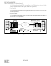
• 24DTI (PA-24DTR) switch setting
Make sure that the keys are properly set on the card. See the NEAX2400 IMX Circuit Card Manual.
If the Fusion link is not established using this repair procedure, perform the Fusion Link Test.
2.2 How to Perform the Fusion Link Test
2.2.1 Fusion Link Test Mode Setting
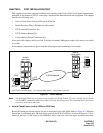
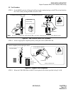
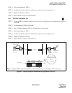
To set the FCH card in Fusion Link Test Mode, set the Mode Switch to 9. Initialize the FCH card using
the MB key. When the Mode is 9, the Fusion Link Controller on the FCH card sends a test data pattern.
When the same pattern is received again the PM activates the LYR LED, flashing the LED at 60-INT,
which means the test result is OK.
Figure 6-3 Fusion Link Test Mode
Note:
Be sure to initialize the FCH (PA-FCHA) card, after changing the setting of the Mode Switch.
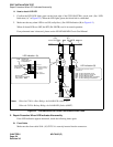
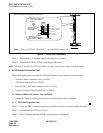
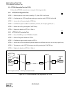
2.2.2 Loopback Point Designation
The DTI card can be set at one of the following loopback points:
1. Internal Loopback
Note:
Loopback points are set by a DTI card.
9
Mode
LYR
9: Fusion Link Test Mode
8: Standard Setting
FCH card
to DTI card
Test is OK
LYR LED flashes.
FCH
front cable
Flow of Test
PA-
FCHA
Send Test
Data Pattern
Receive Test
Data Pattern
FRONT VIEW
Fusion Link Controller sends test data pattern.
DTI Interface
D/I
Fusion Link
Controller
Loopback
Note
To perform a Fusion link test, set the Mode switch to 9.