


ND-70185 (E) CHAPTER 4
Page 39
Revision 3.0
INSTALLATION
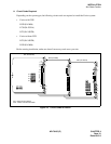
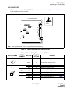
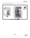
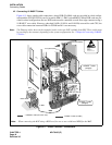
Key Setting on Circuit Cards
Note:
This switch setting is applicable for a system which adopts Associated Channel Interoffice Signalling
(ACIS).
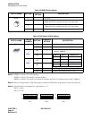
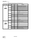
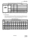
2.4 Digital PAD Setting
The PA-24DTR card is equipped with a mask ROM in which the following typical PAD patterns have been
already written. PAD value is determined by selecting a desired PAD pattern, which can be done by key
setting of the SW 58 (elements 4, 5, 6) on the card, and programming of the PAD data by the ARTD com-
mand - CDN = 30 (PAD). The PAD patterns and ARTD data correspond as follows.
Note:
Stands for 3[dB] GAIN.
SW5D
1
ON
Digital PAD ROM selection: Special specifica-
tion
OFF ×
Digital PAD ROM selection: Standard specifica-
tion
2
ON × LAYER2 signal logic: Positive
OFF LAYER2 signal logic: Negative
3
ON Line fault is not notified to the upper CPU
OFF × Line fault is notified to the upper CPU
4 ON Zero Code Suppression is not provided
Table 4-5 Digital Pad Setting
PAD
DATA
ARTD
CDN=
30
PAD Pattern [dB] (Selected by key setting)
PAD Pattern 1 PAD Pattern 2
A
→µ
Loss
(Bothway)
A
→µ
Loss
(Receive)
µ→
A Loss
(Bothway)
µ→
A Loss
(Receive)
SEND RECEIVE SEND RECEIVE SEND RECEIVE SEND RECEIVE SEND RECEIVE SEND RECEIVE
1
22
-3
Note
300000000
2
4433 4 4 044404
3
6606 6 6 0 12 6 6 0 12
4
8839 8 8 088808
5
Key setting of SW 39-3,4 correspond to PAD values. (Regardless of PAD patterns)
7
0 0 0 0 Through Through Through Through Through Through Through Through
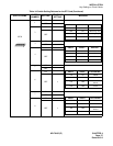
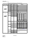
Table 4-4 Switch Setting Patterns for the DTI Card (Continued)
SWITCH NAME
SWITCH
NUMBER
SETTING
STANDARD
SETTING
MEANING
1
2
3
4
OFF