


CHAPTER 8 ND-70185 (E)
Page 190
Revision 3.0
EX- FCCS
Data Programming
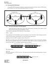
STEP 1: ASYD
Assign the Point Code to all the nodes in the network uniquely as described on Page 163.
STEP 2: ADPCL
Assign the destination PC (Point Code) on LGRT (for speech path) number basis for all the nodes in
the network.
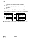
STEP 3: ACSCL
Assign the location of the CCH and FPC of the node which accommodates CCIS trunk in CSCG
(Common Channel Signaling Controller Group) for all the nodes in the network.
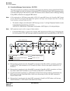
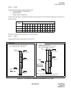
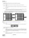
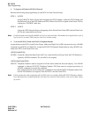
• Assign the location of the CCH using the ACSC command. The following is sample data assignment. In
this sample, PC 3 is equipped with three DTI cards. Note that if the system employs one CCIS link, enter
the same data in CSCG130 and CSCG131.
Note 1:
In the case of actual data entry, enter corresponding LEN numbers instead of letters such as “AAAAA”.
Note 2:
Refer to Figure 8-8 “Port Allocation and Related Command for CCIS Trunk”.
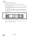
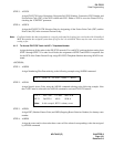
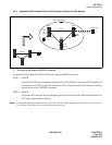
STEP 4: ACIC1
Assign CSCG for Basic/Primary Route. The odd numbered CSCG for alternate Route assignment.
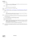
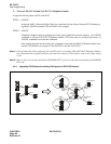
STEP 1: ALRTN
Assign the Logical Route Numbers to all external trunks used in the EX-FCCS network. Assign
unique Logical Route Numbers to the whole routes for external trunks on the network (including
COT, DAT, Dummy route, etc.) using this command. The data must be set at the NCN in each Fusion
Group and is to be set for every external route in all the nodes.
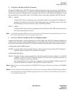
STEP 2: ARSCN
Assign route restriction information according to the Route Restriction Class (RSC) of the Logical
Route Number in the network.
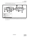
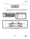
PC CSCG
4 130
<Node which uses CCIS Trunk via Fusion Link (PC1 and PC2 in the example)>
CSCG MG U G CICG
130
(Basic/
Primary
Route)
AAAAA0
BB B BB 1
BB B BB 2
BB B BB 3
BB B BB 4
BB B BB 5
BB B BB 6
BB B BB 7
CSCG MG U G CICG
131
(Alternate
Route)
CCCCC0
CCCCC1
CCCCC2
CCCCC3
CCCCC4
CCCCC5
CCCCC6
CCCCC7
CCH 0
CCH 1
CCH 2
<Network Control Node (PC1 in the example)>