


ND-70185 (E) CHAPTER 4
Page 49
Revision 3.0
INSTALLATION
Connecting Cables
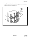
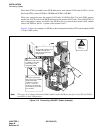
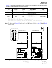
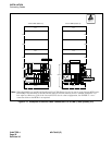
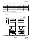
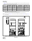
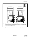
Figure 4-13 shows some typical examples, where 10 BASE-T cables are connected to the FCH card(s) mounted
in PIM0 of 1-IMG system, under the following conditions:
Note 1:
Cables Contained in each cable unit are as follows.
SR1201 ETIF CAU-A: UTP CTG5 ST CA-D, UTP CTG5 ST CA-J
SR1201 ETIF CAU-DA: UTP CTG5 ST CA-D, UTP CTG5 ST CA-J, UTP CTG5 CRS CA-F
Note 2:
The cables cited in Figure 4-13 can be used in the 1-IMG system only. Refer to Page 45 through Page 48
for more details.
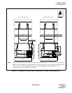
Figure 4-13 Examples of Ethernet Cable Connection-FCH in PIM0 (1-IMG System) (1/2)
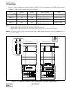
Configuration
of CPU
Configuration
of LAN
Used Cable Unit
(Note 1, Note 2)
Number of HUB/
FCH
Pattern 1 Single Single SR1201 ETIF CAU-A × 1 HUB× 1, FCH× 1
Pattern 2 Dual Single
SR1201 ETIF CAU-A × 1
SR1201 ETIF CAU-DA × 1
HUB× 2, FCH× 2
Pattern 3 Single Dual SR1201 ETIF CAU-A × 2 HUB× 2, FCH× 2
Pattern 4 Dual Dual
SR1201 ETIF CAU-A × 2
SR1201 ETIF CAU-DA × 2
HUB× 2, FCH× 2
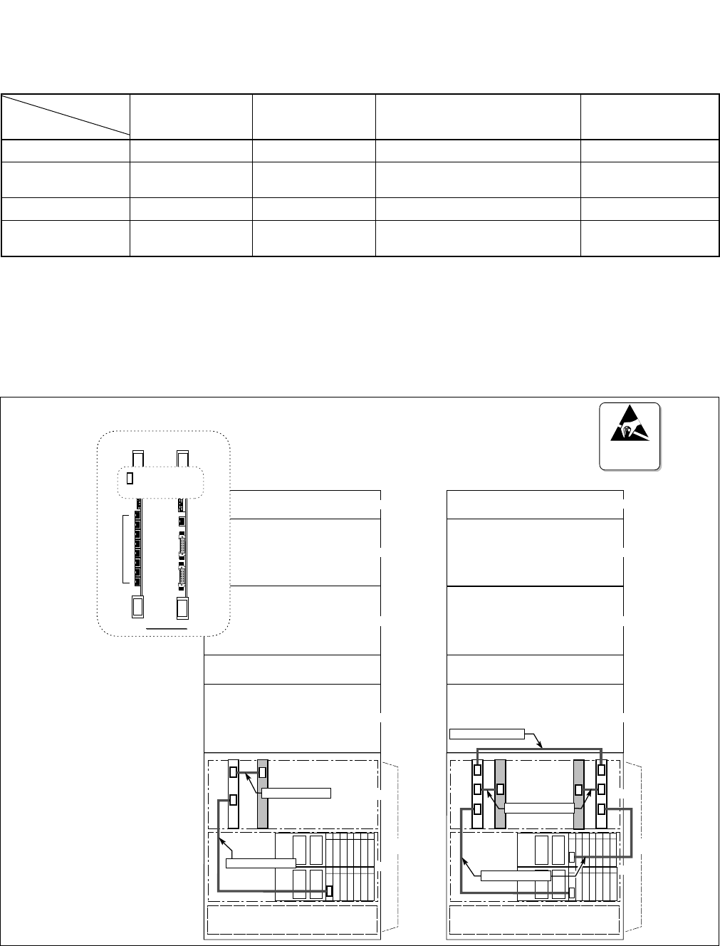
ATTENTION
Contents
Static Sensitive
Handling
Precautions Required
BSCM
06040503020100
06040503020100
CN
CN
HUB
BASEU
PIM 1
PIM 2
PIM 3
UTP CTG5 ST CA-J
PIM 0
LPM
FANU
FCH
CN
CN
UTP CTG5 ST CA-D
TOPU
FCH
(PA-FCHA)
HUB
(PA-M96)
TP0-X
TP1-X
TP2-X
TP3-X
TP4-X
TP5-X
TP6-X
TP7-X
10 BASE-T
Connectors for 10 BASE-T
FRONT VIEW
FRONT VIEW
CN
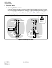
= 10 BASE-T Connector
Use 10 BASE-T connectors.
BSCM
06040503020100
06040503020100
CN
CN
CNCN
UTP CTG5 ST CA-J
CN
FCH
HUB
CN
CN
HUB
BASEU
PIM 1
PIM 2
PIM 3
LPM
CN
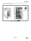
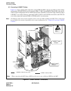
<FCH in PIM0 (Pattern 1)> <FCH in PIM0 (Pattern 2)>
PIM 0
UTP CTG5 CRS CA-F
CN
FCH
CN
UTP CTG5 ST CA-D
TOPU
FANU