


CHAPTER 4 ND-70185 (E)
Page 44
Revision 3.0
INSTALLATION
Connecting Cables
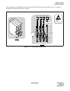
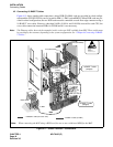
4.2 Connecting 10 BASE-T Cables
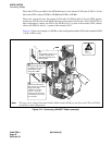
Figure 4-11 shows sample cable connections, where HUB (PA-M96) cards are provided in a dual configu-
ration and the FCH (PA-FCHA) card is located in PIM 1 (1-IMG system/IMG0). When HUB cards are pro-
vided in a dual configuration, the two HUB cards must be connected on each front edge connector using a
10 BASE-T cross cable. However, when dual LANIs (LANI-A and LANI-B) are used for each CPU, the
cross cable connection between HUBs for FCH#0 and #1 is not necessary.
Note:
The Ethernet cables shown in the examples in this section are NOT available from NEC. These cables must
be provided by the customer, depending on the system configuration. See “Chapter 6 Connecting 10 BASE-
T Cables.”
Figure 4-11 Overall 10 BASE-T Connections
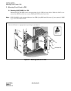
ATTENTION
Contents
Static Sensitive
Handling
Precautions Required
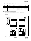
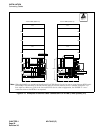
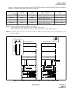
DTI (PA-24DTR)
DTI
LANI (PZ-PC19)
LANI (PZ-PC19)
10 BASE T cable
(straight)
10 BASE T cable
(straight)
: 10 BASE-T cable (for Fusion Link)
: 10 BASE-T cable (for MAT)
MAT
PIM 1
PIM 0
HUB
(PA-M96)
HUB
(PA-M96)
HUB
(PA-M96)
GT
GT
to MAT
REAR VIEW
Note
10 BASE T cable
(cross)
FCH (PA-FCHA)
Note:
When connecting the MAT using a HUB card, be sure to use a dedicated HUB for the MAT.