


CHAPTER 8 ND-70185 (E)
Page 182
Revision 3.0
EX- FCCS
EX-FCCS Features
3.4 Centralized Message Center Interface - EX-FCCS
This section explains the conditions of Centralized Message Center Interface feature within EX-FCCS Net-
work. This feature provides an interface to the external CPU for Message Center (MC) information when
a specified UCD group in the network is called. This interface allows external control of Message Waiting
Lamp (MWL) indications on equipped PBX stations.
Note:
Calls terminated to a UCD hunt group within a FUG will output MCI data to the Centralized MCI output
port for that FUG if assigned. Each FUG that requires a message center interface must have a message
center interface assigned within the FUG,
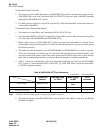
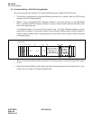
• The number of digits to be indicated for MCI message (in case 7 or 8-digit Telephone Number is used)
is determined by the following system data.
ASYD SYS1, INDEX246, b3. Maximum valid number of MCI digits is, 0/1=6 digits/8 digits.
Note:
MCI equipment must be able to support 8-digit numbers.
• Centralized MCI feature is activated by assigning MCI equipment and UCD group at Centralized Of-
fice for the specific FUG. (MCI message cannot be transferred to the Centralized Office via EX-FCCS.)
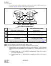
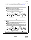
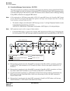
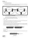
(a) Message data is transferred to the offered MCI (connected to Node B) in FUG1, given that a call from
a station in IVS
2
node terminates to a UCD station (in Node A shown in the figure) within FUG1 via
EX-FCCS.
(b) Message data is transferred to the offered MCI (connected to Node B) in FUG1, given that a call from
any station within FUG2 terminates to a UCD station within FUG1 via EX-FCCS.
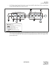
(c) If a call from Node F terminates to a UCD station in Node E, the message cannot be transferred to the
MCI connected to the Centralized Office. In this case, the message is sent to the MCI connected to
Node H within FUG2.
(d) Message data is transferred to the shared MCI (connected to Node H) in FUG2 when a call from any
station terminates to a UCD station in the same Fusion Group.
Node
A
Node
C
Node
D
Node
E
MCI
MCI
FUG1 (Center FUG)
FUG2
IVS
(a)
UCD
B
Node
Node
H
EX-FCCS
FCCS (Fusion Call Control Signal)
Direction of a call
Direction of MCI message
Node
G
Node
F
UCD
UCD
(b)
(c)
(d)
2
IVS
2
Enhanced CCIS