


173
Using the BayStack 420 10/100/1000 Switch
Chapter 4
Troubleshooting
This chapter describes how to isolate and diagnose problems with your BayStack
420 Switch and covers the following topics:
• “Interpreting the LEDs,” next
• “Diagnosing and correcting problems” on page 175
— Normal power-up sequence
— Port connection problems
The chapter topics lead you through a logical process for troubleshooting the
BayStack 420 Switch. For example, because LEDs provide visual indications
of certain problems, see “Interpreting the LEDs” on page 173 to understand the
various states (Table 42) that your switch LEDs can exhibit during normal
operation.
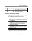
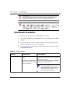
For more help in determining the problem, “Diagnosing and correcting problems”
on page 175 describes symptoms and corrective actions (Table 43) you can
perform to resolve specific problems. Subsequent sections give step-by-step
procedures to correct the problems.
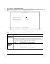
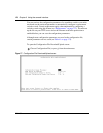
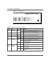
Interpreting the LEDs
Figure 78 shows the BayStack 420 Switch LED display panel. Table 42 describes
the LEDs.