


Chapter 2 Network configuration 53
Using the BayStack 420 10/100/1000 Switch
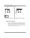
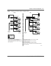
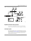
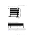
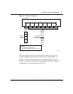
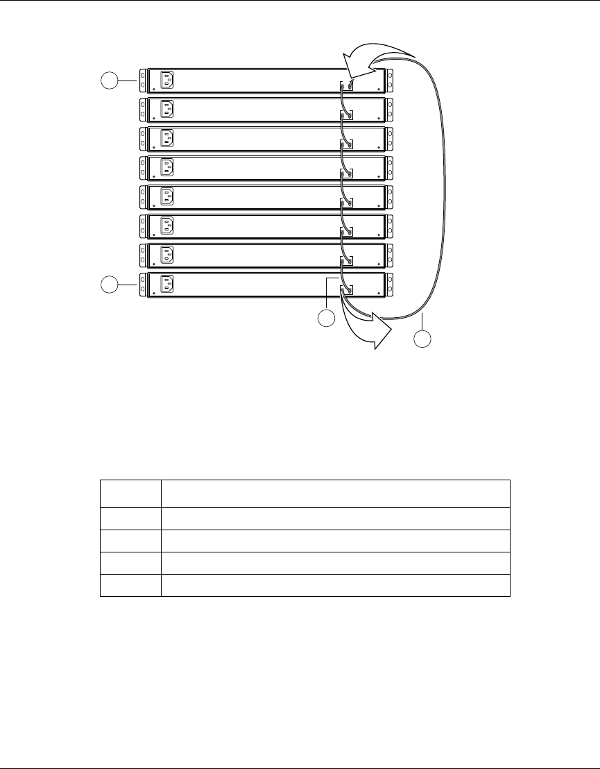
Figure 10 Stack down configuration example
Table 8 describes the stack down configuration illustration references.
Certain network management station (NMS) applications assume a stack down
configuration for the graphical user interface (GUI) that represents the stack (see
Figure 10). For this reason, Nortel Networks recommends that you always
configure the top unit in the stack as the base unit.
Table 8 Stack down configuration description
Item Description
1 Base unit
2 Last unit
3 Stacking cable 30 cm (order number AL 2018005)
4 Stacking max-return cable 1 m (part number AL 2018006)
Unit 1
Unit 2
Unit 3
Unit 4
Unit 5
Unit 6
Unit 7
Unit 8
1
10002EA
4
100-240 V-
50-60Hz 2A
Out In
Cascade
2
100-240 V-
50-60Hz 2A
Out In
Cascade
100-240 V-
50-60Hz 2A
Out In
Cascade
100-240 V-
50-60Hz 2A
Out In
Cascade
100-240 V-
50-60Hz 2A
Out In
Cascade
100-240 V-
50-60Hz 2A
Out In
Cascade
100-240 V-
50-60Hz 2A
Out In
Cascade
100-240 V-
50-60Hz 2A
Out In
Cascade
In
Out
3