


Chapter 2 Network configuration 59
Using the BayStack 420 10/100/1000 Switch
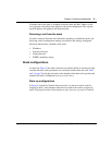
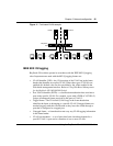
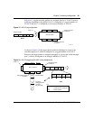
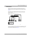
In Figure 15, tagged incoming packets are assigned directly to VLAN 2 because
of the tag assignment in the packet. Port 5 is configured as a tagged member of
VLAN 2, and port 7 is configured as an untagged member of VLAN 2.
Figure 15 802.1Q tag assignment
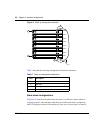
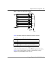
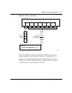
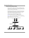
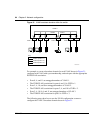
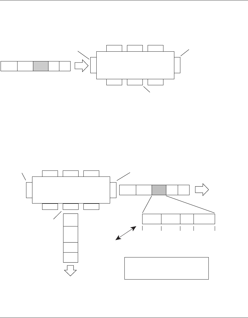
As shown in Figure 16, the tagged packet remains unchanged as it leaves the
switch through port 5, which is configured as a tagged member of VLAN 2.
However, the tagged packet is stripped (untagged) as it leaves the switch through
port 7, which is configured as an untagged member of VLAN 2.
Figure 16 802.1Q tagging (after 802.1Q tag assignment)
Port 6
DASATagDataCRC
Tagged packet
BS45013A
Port 7 Port 8
Port 1
Port 4
Port 5
Port 2 Port 3
802.1Q Switch
PVID = 2
Untagged member
of VLAN 2
Tagged member
of VLAN 2
Before
BS45014A
Port 6 Port 7 Port 8
Port 1
Port 4
Port 5
Port 2 Port 3
802.1Q Switch
Key
Priority
CFI
VID
- User_priority
- Canonical format indicator
- VLAN identifier
PVID = 2
Tagged member
of VLAN 2
Untagged member
of VLAN 2
After
DA
SA
Data
CRC*
(*Recalculated)
Outgoing
untagged packet
changed
(tag removed)
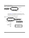
DASADataCRC Tag
VID = 2Priority
16 bits 3 bits 1 bit 12 bits
8100 CFI