


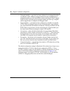
52 Chapter 2 Network configuration
209418-A
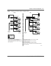
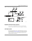
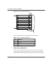
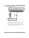
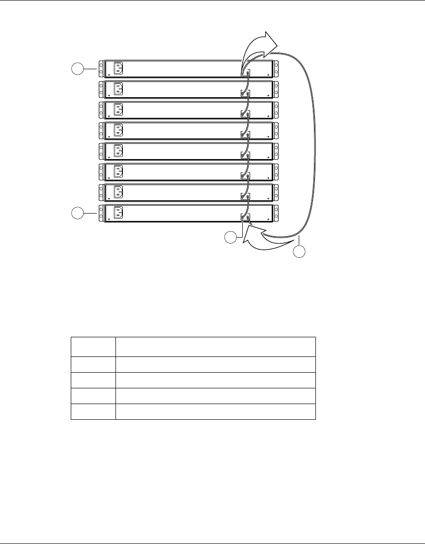
Figure 9 Stack up configuration example
Table 7 describes the stack up configuration illustration references.
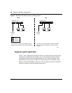
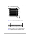
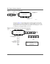
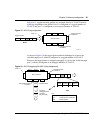
Stack down configurations
In Figure 10, data flows from the base unit (unit 1) to the next switch, which is
assigned as unit 2, and continues until the last switch in the stack is assigned as
unit 8. The physical order of the switches is from top to bottom (unit 1 to unit 8).
Table 7 Stack up configuration description
Item Description
1 Last unit
2 Base unit
3 Stacking cable 30 cm (order number AL 2018005)
4 Stacking cable 1 m (order number AL 2018006)
Unit 8
Unit 7
Unit 6
Unit 5
Unit 4
Unit 3
Unit 2
Unit 1
1
10001EA
4
100-240 V-
50-60Hz 2A
Out In
Cascade
2
100-240 V-
50-60Hz 2A
Out In
Cascade
100-240 V-
50-60Hz 2A
Out In
Cascade
100-240 V-
50-60Hz 2A
Out In
Cascade
100-240 V-
50-60Hz 2A
Out In
Cascade
100-240 V-
50-60Hz 2A
Out In
Cascade
100-240 V-
50-60Hz 2A
Out In
Cascade
100-240 V-
50-60Hz 2A
Out In
Cascade
3
In
Out