


72 Chapter 2 Network configuration
209418-A
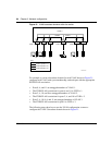
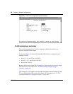
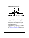
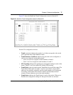
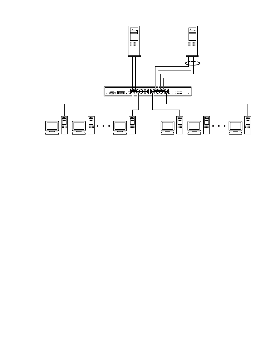
Figure 28 Switch-to-server trunk configuration example
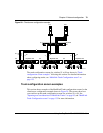
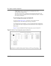
Client/server configuration using MultiLink Trunks
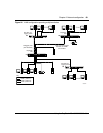
Figure 29 shows an example of how MultiLink Trunking can be used in a
client/server configuration. In this example, both servers connect directly to
Switch S1. FS2 is connected through a trunk configuration (T1). The
switch-to-switch connections are through trunks (T2, T3, T4, and T5).
Clients accessing data from the servers (FS1 and FS2) are provided with
maximized bandwidth through trunks T1, T2, T3, T4, and T5. Trunk members
(the ports making up each trunk) do not have to be consecutive switch ports; you
can select ports randomly, as shown by T5.
With spanning tree enabled, one of the trunks (T2 or T3) acts as a redundant
(backup) trunk to Switch S2. With spanning tree disabled, you must configure
trunks T2 and T3 into separate VLANs for this configuration to function properly
Refer to “IEEE 802.1Q VLAN workgroups” on page 54 for more information.
S1
FS1
FS2
T1
10010EA
BayStack
420