


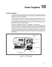


11-1
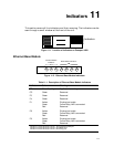
Indicators 11
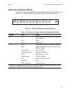
This section covers all the indicators and their meaning. The indicators can be
seen through a small window at the front of the unit.
Figure 11-1. Location of Indicators on Passport 4400
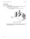
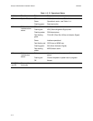
Ethernet Base Module
Figure 11-2. Ethernet Base Module Indicators
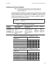
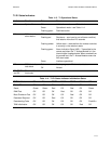
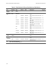
Table 11-1. Description of Ethernet Base Module Indicators
Indicator Color Meaning
CP Green-flashing Application is running
CC Green Reserved
F3 Green Reserved
F4 Green Reserved
P1 Amber
Green
Red
Physical port exists
Frame Relay LMI is connected
Reserved
P2 Amber
Green
Red
Physical port exists
Frame Relay LMI is connected
Reserved
P3 Amber
Green
Red
Physical port exists
Frame Relay LMI is connected
Reserved
Indicator P1 shows the status of Port 1, the Frame Relay DCE port.
Indicator P2 shows the status of Port 2, the MPANL port.
Indicator P3 shows the status of Port 3, the backup port.
Indicators
P2 P1 F4 F3 CC CP
Base Module Indicators
P3
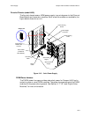
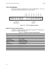
Interface Module
Indicators