


T1/E1 and Digital Voice Modules Passport 4400 Hardware Installation Manual
9-3
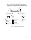
Connectors
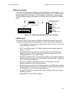
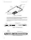
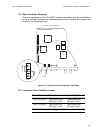
Figure 9-4. Pin Assignments for T1 Voice Module
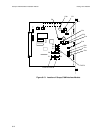
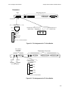
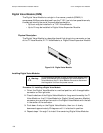
Figure 9-5. Pin Assignments for E1 Voice Module
Test
DSX-1
Interface
RJ48 Interface
Pin 1
Transmit Pair to T1
(Monitor Only)
Transmit Pair from T1
(Monitor Only)
Reserved for future use
1
2
3
4
5
6
7
8
Ring (R)
Tip (T)
Ring 1 (R1)
Tip 1 (T1)
RJ48
Pins 3, 6, 7, 8 Not Connected
Line 1 (DSC-1)
E1 Interface
Connectors
For 75 Ω Interface
Receive
Pair
Transmit
Pair
DB9 Connector
For120
ΩBalanced
pair Interface
1
2
3
4
5
6
7
8
Tx Tip
Rx Tip
Tx Ring
Rx Ring
Reserved for Future use
Pins 2, 4, 5, 7 Not Connected