


Analog Voice Modules Passport 4400 Hardware Installation Manual
8-15
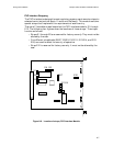
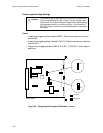
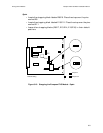
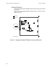
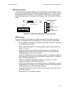
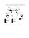
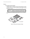
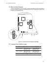
Figure 8-17, “Telephone Interface Cable Connections,” shows the connector
locations, pin assignments and wire colors of a dual channel AVM. Single channel
modules have only one set of interface connectors. Use a modular cable to connect
to the applicable telephone interface. Cables are supplied.
Figure 8-17. Telephone Interface Cable Connections
Analog Voice
Module
Pin 1
RJ11
Pin 1
Modular cable for E&M
(FXO). Connecttoterminal
block associated with the
PBX.
ModularcableforFXSor FXO.
Connect to telephone set or
wall jack.
FXS/FXO
RJ11 Interface
E&M
RJ1CX Interface
RJ1CX
Voice/Fax
Channel 2
Voice/Fax
Channel 1
RJ11Pin Assignmentsand
Wire Colors
1
2
3
4
Ring (R), red
Tip (T), green
RJ1CXPinAssignmentsand
Wire Colors (4-wire)
1
2
3
4
5
6
7
8
Signal Battery (SB), blue
Mouth (M), orange
Ring 1 (R1), black
Ring (R), red
Tip (T), green
Tip 1 (T1), yellow
Ear (E), brown
Signal Ground (SG), gray
RJ1CXPin Assignmentsand
Wire Colors (2-wire)
1
2
3
4
5
6
7
8
Signal Battery (SB), blue
Mouth (M), orange
Ring (R), red
Tip (T), green
Ear (E), brown
Signal Ground (SG), gray
Blue SB
lead
Pins 1, 4 Not Connected
Pins 3, 6 Not Connected