


Installing the Passport 4400 Passport 4400 Hardware Installation Manual
2-7
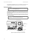
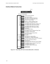
Verifying Operation
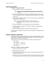
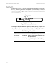
All indicators can be seen through a series of small windows at the front of the
chassis (see Figure 2-9 and Table 2-2 below). The bottom window contains status
indicators for the Ethernet Base Module, in addition to any serial interface
modules that are installed.
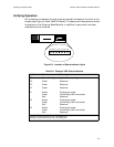
Figure 2-9. Location of Status Indicator Lights
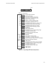
Table 2-2. Passport 4400 Status Indicators
Indicator Color Meaning
CP Green-flashing Application is running
CC Green Reserved
F3 Green Reserved
F4 Green Reserved
P1 Amber
Green
Red
Physical port exists
Frame Relay LMI is connected
Reserved
P2 Amber
Green
Red
Physical port exists
Frame Relay LMI is connected
Reserved
P3 Amber
Green
Red
Physical port exists
Frame Relay LMI is connected
Reserved
Indicator P1 shows the status of Port 1, the Frame Relay DCE port.
Indicator P2 shows the status of Port 2, the MPANL port.
Indicator P3 shows the status of Port 3, the backup port.
P3 P2 P1 F4 F3 CC CP