


Connecting the Expansion Modules Passport 4400 Hardware Installation Manual
4-7
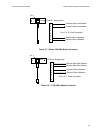
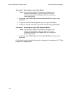
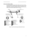
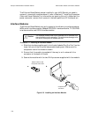
Analog Voice Module (AVM)
Prior to connecting the Analog Voice Module (AVM), ensure that the interface
type/signaling convention has been properly strapped (refer to Section 8, “Analog
Voice Modules”). The connection procedure is identical for modules with either
single or dual channels, although modules with the dual channel feature may be
configured for two different types of signaling conventions.
Figure 4-7. Rear View of the Analog Voice Module (Dual Channel)
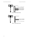
ClearVoice
Module
Pin 1
RJ11
Pin 1
Modular cable for E&M.
Connect to terminal block
associated with the PBX.
ModularcableforFXSor FXO.
Connect to telephone set or
wall jack.
FXS/FXO
RJ11 Interface
E&M
RJ1CX Interface
RJ1CX
Voice/Fax
Channel 2 (dual channel model only)
Voice/Fax
Channel 1
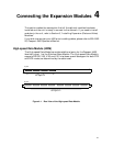
RJ11Pin Assignmentsand
Wire Colors
1
2
3
4
Ring (R), red
Tip (T), green
RJ1CXPinAssignmentsand
Wire Colors (4-wire)
1
2
3
4
5
6
7
8
Signal Battery (SB), blue
Mouth (M), orange
Ring 1 (R1), black
Ring (R), red
Tip (T), green
Tip 1 (T1), yellow
Ear (E), brown
Signal Ground (SG), gray
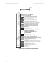
RJ1CXPin Assignmentsand
Wire Colors (2-wire)
1
2
3
4
5
6
7
8
Signal Battery (SB), blue
Mouth (M), orange
Ring (R), red
Tip (T), green
Ear (E), brown
Signal Ground (SG), gray
Blue SB
lead
Pins 1, 4 Not Connected
Pins 3, 6 Not Connected