


Connecting the Expansion ModulesPassport 4400 Hardware Installation Manual
4-6
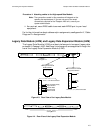
E1 Voice Module (EVM)
Note: Before you can connect this module, the E1 Voice Module
location switch must be set for slot B. If your Passport 4400 unit
has been factory assembled, the switch has already been set for
slot B. Refer to section 6, “Installing Expansion (Data and Voice)
Modules,” for further information.
This module can be connected with either a 75 Ω termination or a 120 Ω
termination. These terminations are determined by jumper settings on the
module board. Ifyou are unsurehowthese jumpersareset orifyou want to change
the settings on the unit you have received, see section 9 before connecting this
module.
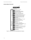
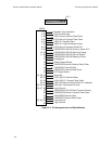
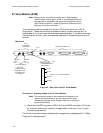
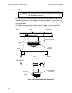
Figure 4-6. Rear View of the E1 Voice Module
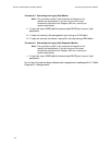
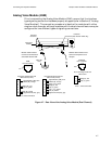
Procedure 8: Attaching cables to the E1 Voice Module
Note: The connections made in this procedure will depend on the
specific site requirements. If you are not sure of the exact
connections required for the Passport 4400 unit, consult your
system administrator.
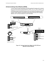
1. Use either the DB9 connector (120 Ω) or the two BNC connectors (75 Ω, one
for transmit and one for receive), as applicable, to connect Line 1 to your
interfacing equipment.
For further informationaboutcablesand pin assignments, see AppendixA,“Cable
Diagram Pin Assignments.”
Rear Panel
Line 1
E1 Interface
Connectors
For 75 Ω Interface
Receive
Pair
Transmit
Pair
DB9 Connector
For120
ΩBalanced
pair Interface
1
2
3
4
5
6
7
8
9
Tx Tip
Rx Tip
Tx Ring
Rx Ring
(The outer
conductor can be
strappedforearth
or isolated. Refer
to section 9.
Reserved for future use
Pins 2, 4, 5, 7, 9 Not Connected
Pin 1