


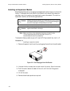

Installing Expansion (Data and Voice) ModulesPassport 4400 Hardware Installation Module
6-2
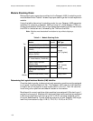
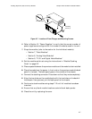
Module Stacking Order
Before placing any expansion modules into the Passport 4400, the stacking order
must be determined.Table 6-1shows the properstackingorder foreachexpansion
module.
Using the table, determine the stacking order for your Passport 4400 expansion
modules. For instance, a Passport 4400 unit with a T1 Voice Module (TVM), an
Analog Voice Module (AVM), and a High-Speed Data Module (HDM) would have
the HDM in the bottom slot, followed by the TVM and the AVM.
Note: Modules must be stacked from bottom to top, without skipping a
slot.
Table 6-1. Module Stacking Order
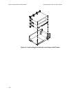
Determining the Logical Interface Module (LIM) Identifier
Once the stacking order is determined, each expansion module must be assigned
to a Logical Interface Module (LIM). The Passport 4400 uses the LIM identifier
to keep track of the position of each module within the unit. The LIM identifier
is set using a four-position switchbank located on the module.
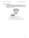
Modules with numeric switches (data modules) are assigned LIMs starting at 1
and continuing up to 4. Moduleswith alpha switches (voice modules)are assigned
LIMs starting at B and continuing up to E (LIM A is already assigned to the
Ethernet Base Module). Typical stacking orders for a 5-slot Passport 4400 might
look like (from bottom to top) 1-2-B-C, 1-B-C-D, 1-2-3-B, or B-C-D-E.
Module
Max No.
in unit LIM Type
Analog Voice Module (AVM) 4 Alphabetical:
LIM B (lowest)
through
LIM E (highest)
UniversalAnalogVoice Module
(UAVM)
4
Digital Voice Expansion
Module (DVEM)
2
T1 Voice Module or
E1 Voice Module (TVM/EVM)
1
Legacy Data Expansion
Module (LEM)
2 Numeric:
LIM 1 (lowest)
through
LIM 4 (highest)
Legacy Data Module (LDM) 1
High-speed Data Module
(HDM)
2
Ethernet Base Module (EBM) 1 Always LIM A
Top
Bottom