


Cable Diagram Pin Assignments Passport 4400 Hardware Installation Manual
A-15
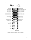
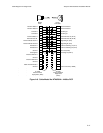
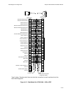
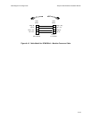
Figure A-12. Cable Model No. NTAU24AA - 4400 to DCE
NC NC
37-Pin
V.36 Male
To 4400
To Data Communication
Equipment (DCE)
MD50 Male
Type 2 cables: Receivers shall have one terminal connection for each input terminal at the
load interchange point.
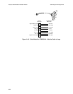
Receive Data B (TD A) 20 6
Receive Data B (TD B) 45 22
Receive Clock A 22 17
Receive Clock B 47 35
External Transmit Data Clock A 8 8
External Transmit Data Clock B 33 26
Transmit Data A 6 6
Transmit Data B 31 22
External Clock A 21 5
External Receive Data Clock B 32 23
Clear to Send A 9 9
Cleart to Send B 34 20
Data Set Ready A 10 11
Data Set Ready B 35 20
Carrier Detect A 11 13
Carrier Detect B 36 20
Request to Send 12 7
Ground 48 25
Receive Clock A 22 8
Receive Clock B 47 26
Unassigned 13 16
Ground 49 30
Gournd 50 34
Data Terminal Ready 37 12
DTE COM 18 37
Ground 43 19
DCE COM 19 34
Interface Tape Indication A 1
Ground 26
Cable Present Status 14
Ground 39