


T1/E1 and Digital Voice ModulesPassport 4400 Hardware Installation Manual
9-2
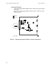
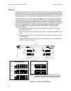
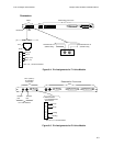
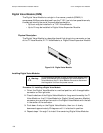
Figure 9-1. T1/E1 Voice Module
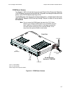
On the right front are 13 indicators. Of these, the six on the left are associated
with the voice/fax channels represented by the six Digital Voice Modules, while
the seven on the right are associated with the Voice Module.
At the centerand on the right side are four feed-through stacking connectors used
to connect the Voice Module to the base unit module below it and to any expansion
module above it.
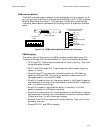
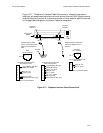
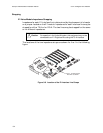
Figure 9-2. T1 Voice Module Rear Panel
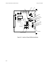
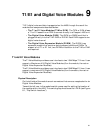
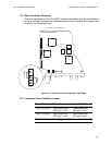
Figure 9-3. E1 Voice Module Rear Panel
Rear
(Back Panel)
Front
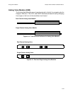
Module
Switch Group
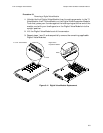
Receptacles (6) for
Digital Voice Modules
Stacking Connectors
Indicators
Test
DSX-1
Interface
Reserved for future use
Line 1 E1
Interface
Connectors
Reserved for future use