


Page: 75
Service Guide ML520/521
Chapter 3 Maintenance & Disassembly
3.2.06 Upper Cover, Access Cover, and Sheet Guide Assemblies
1.
Perform this procedure: 3.2.01.
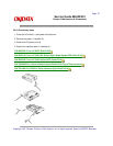
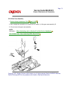
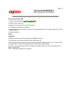
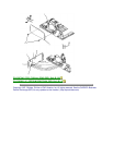
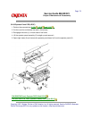
2. Pull the platen knob (1) straight out and remove it.
3. Set the change lever (2) to the bottom feed position (toward the rear of the printer).
4. Insert a flat-blade screwdriver into the grooves (3) of the frame and pry the upper cover (4) away from
the frame.
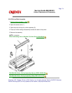
5. Raise the front side of the upper cover assembly.
6. Tilt the upper cover assembly toward the rear to disengage the claws (not shown) at the rear of the
frame.
7. Lift the upper cover assembly and remove it.
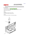
CAUTION:
Do not rotate the access cover past the vertical when removing it or you will break the tab extensions.
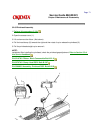
8. Raise the access cover assembly (5) until it is vertical, then lift it straight up to remove it.
9. Remove the sheet guide assembly (6).
10. Note the position of the cover (B) [for card slot] (7). This is part of the upper cover and should not be
removed. No font cards are currently available.
CAUTION:
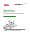
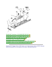
When installing the upper cover, make sure that the sensors correctly contact the control board (3.2.07).
The cut sheet/continuous sensor lever must be positioned below the BASW sensor. The lever should
contact the sensor only when the change lever is in the top feed (middle) setting. If the lever is not
correctly positioned, the ALARM lamp will light and the unit will not automatically load paper or receive
data.
When cleaning, refer to Section 3.4 of this Service Handbook.